SVG Won't Extrude: Fix Open Paths and Broken Profiles
An SVG will not extrude when its paths fail to define a usable face. Find open endpoints, line-only art, overlaps, holes, and excessive nodes before converting formats.
On this page
An SVG can look complete and still refuse to extrude. The usual reason is that the imported curves do not define a closed, valid profile. A gap too small to see, a centerline with no enclosed area, a self-intersection, or duplicate segments can stop CAD software from finding a face.
The quickest test is not another export. Try to select the area inside the outline. In Fusion, the 3D Sketch documentation explains that closed planar curves create shaded profiles. If you can select only the lines, diagnose the boundary before changing file formats.
Check these before converting to DXF
- Is the inside of the shape recognized as a profile?
- Are all intended boundaries closed endpoint to endpoint?
- Is the artwork a centerline that needs width rather than a filled outline?
- Do paths cross themselves or sit directly on duplicates?
- Are holes represented as holes instead of separate filled objects?
- Is the sketch so dense that the CAD importer struggles to solve it?
An outline is not always a profile
Vector editors are forgiving display tools. They can render a stroke along an open path, and a fill may visually close an open contour between its last and first point. CAD software has a different job. It needs a bounded region that can become a face, then a solid.
That creates three common cases:
| What you see | What the file may contain | Extrusion result |
|---|---|---|
| A filled logo shape | One or more closed boundaries | Usually a selectable profile |
| A thin drawn line | An open centerline with a stroke | No face to extrude as a slab |
| A complete-looking outline | A nearly closed path with a tiny endpoint gap | Lines import, but no profile appears |
If the design is supposed to be a thin rail, wire, or engraved line, a sweep, pipe, or stroke-to-path workflow may fit better than a normal face extrusion. If it should be a flat badge or raised logo, it needs enclosed regions.
A heavy stroke can still be only a visual treatment on an open centerline. The extrusion test cares about topology: connected boundaries must enclose a face before the CAD tool can turn that area into a solid.
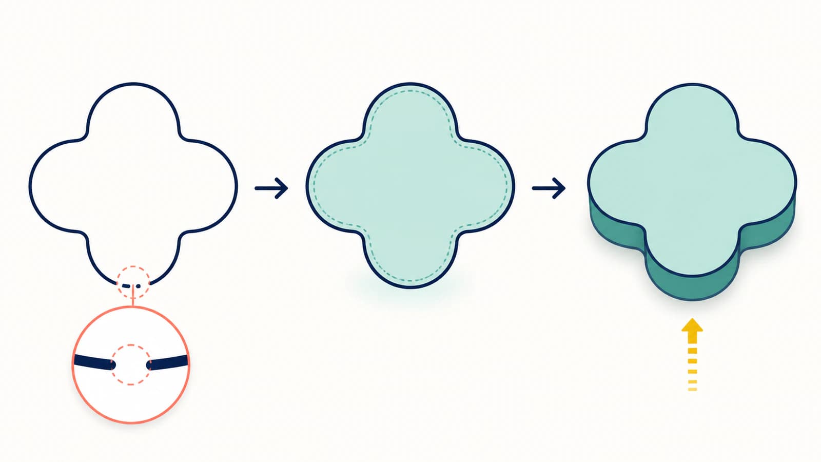
This is related to the double-line problem in cutting SVGs, but the desired geometry differs. A cutter may need one centerline. An extruded slab needs an area between boundaries.
Find an open endpoint
Tiny breaks cause a large share of failed profiles. Work on a copy and use this sequence:
- Zoom into corners and joins with node or point editing enabled.
- Turn on endpoint indicators if the editor provides them.
- Check whether adjoining points only look aligned or are actually joined.
- Snap or join the correct pair of endpoints.
- Reimport and test whether the enclosed area becomes selectable.
In CAD, a temporary line can speed up the search. Draw a line across the suspect region. If one side becomes a valid shaded profile, the break is on the other side. Move the divider until you isolate the faulty segment.
Do not close every open path automatically. Letter strokes, engraving lines, and deliberate openings may be correct. Close only the boundaries intended to create faces.
Check crossings, duplicates, and microscopic loops
A path can be closed yet still fail as a useful profile.
- Self-intersections make the inside ambiguous where a curve crosses itself.
- Duplicate segments put two edges in the same place and can confuse profile detection.
- Overlapping shapes may create sliver regions instead of one clean face.
- Microscopic loops often come from noisy tracing and produce tiny unwanted profiles.
- Stray paths outside the artwork can enlarge the sketch bounds or add solver work.
Use outline or wireframe view, hide fills, and select by path. Delete confirmed duplicates, split and rejoin self-crossing curves, and unite shapes that should be one region. Keep separate regions when they represent separate bodies or colors.
If the file lights up with hundreds of points along simple curves, read the too-many-nodes diagnosis. Simplification can help, but compare the result against the original because aggressive settings can move corners and close small holes.
Preserve holes and counters
The center of an O, the triangle inside an A, and the hole in a washer must remain empty when the outer shape extrudes. In SVG, those holes may be expressed as subpaths in one compound path or as separate shapes whose fill behavior creates the opening.
After import, confirm both boundaries are present and that the region between them is selectable. If the whole letter becomes solid, the importer may not have preserved the compound relationship. Rebuild the compound path or subtract the inner profile in CAD.
Do not merely recolor the inner shape white. White is still a filled shape, not an instruction to create a hole.
Make sure the SVG contains vector geometry
Some files use the .svg extension but contain an embedded PNG or another web feature rather than ordinary paths. A browser can display that file, while CAD imports nothing useful.
Open the SVG in a text editor and search for common elements:
<!-- Geometry CAD can usually import as curves -->
<path d="M10 10 L90 10 L90 90 L10 90 Z" />

<!-- A raster picture inside an SVG container -->
<image href="data:image/png;base64,..." />
An <image> element embeds image content rather than defining the boundary geometry needed for a profile; the SVG embedded-content specification defines this distinction. Go back to the original raster and vectorize it into paths, or redraw the design if dimensions and lettering must be exact. The guide to SVGs that still contain pixels shows how to confirm the difference.
A repair order that avoids wasted work
Use the smallest correction that makes the intended profile valid:
- Preserve the original SVG.
- Confirm that real paths imported.
- Test whether the interior is selectable.
- Join only unintended endpoint gaps.
- Remove duplicates and self-intersections.
- Rebuild compound holes where needed.
- Simplify excessive nodes conservatively.
- Check scale and units.
- Extrude a shallow test before building the full part.
Converting to DXF can help when the destination supports DXF more reliably, but it does not automatically repair an open contour. Inspect the converted sketch with the same profile test.
For OpenSCAD, apply the SVG import checks after repairing the profile. For an on-screen mesh, the Three.js SVGLoader walkthrough shows a separate browser workflow with a tested opening, orientation, and size.
Where PerfectVector fits
When the source is a PNG or JPG, the SVG for 3D printing workflow converts visible artwork into editable vector paths and provides a preview before download. It is best suited to flat logos, lettering, symbols, and other designs with clear regions.
The preview is the moment to inspect silhouettes, holes, and path complexity. PerfectVector creates the 2D vector; your CAD or slicer still decides which profiles are valid and turns them into 3D bodies. Tiny text, hairline details, and photographic shading may need cleanup or a different 3D method.
The full image-to-SVG for 3D printing guide covers source preparation, import, and final extrusion across common tools.
FAQ
Why can I see my SVG in Fusion but not select it to extrude? The curves probably imported, but they do not form a closed profile. Look for an unshaded interior, open endpoints, duplicate segments, or self-intersections. Join the actual break, reimport, and confirm the area becomes selectable before trying the extrude command again.
Can an open SVG path be extruded? An open path cannot create a normal filled face by itself. It may drive a sweep, pipe, or engraving operation, depending on the tool. To extrude a flat slab, give the line width as closed outline geometry or build a closed boundary around the intended area.
Why does SVG text import but refuse to extrude? Outlined letters can contain broken contours, overlapping shapes, duplicate edges, or incorrectly represented counters. Convert text to clean outlines in the source app, preserve the holes inside letters, then test each letter as a selectable profile.
Will converting SVG to DXF fix an open path? Usually not. DXF may be a better exchange format for a particular CAD tool, but conversion can preserve the same gap or duplicate line. Diagnose the geometry first and verify the DXF profile after import.
How many nodes are too many for extrusion? There is no universal limit. The warning sign is simple geometry represented by hundreds or thousands of points, especially when the sketch solves slowly or fails to select. Reduce nodes only while corners, curves, and small holes remain correct.
Sources
- Autodesk Fusion — Create a 3D sketch — Documents shaded profiles formed by closed planar curves.
- Autodesk Fusion — Extrude a solid body — Documents selecting sketch profiles for solid extrusion.
- Autodesk Fusion — Insert SVG — Documents importing SVG geometry into a sketch.
- W3C — SVG 2 Embedded Content — Defines the SVG
<image>element used to embed raster content.
Have a flat raster design instead of usable paths? Convert it to an SVG for 3D printing, inspect the holes and outline in the vector preview, then run the selectable-profile test in your CAD or slicer before building the final solid.
More from the blog

PNG to SVG for Bambu Studio: Clean Multicolor Imports
Convert a PNG to SVG for Bambu Studio, preserve useful color regions, check closed paths and holes, then verify size and extrusion before you slice the model.

How to Check an SVG File Before You Cut It (or Buy It)
The five-minute preflight for cut files: spot fake vectors, doubled paths, node bloat, and stray boxes before you waste vinyl, plus what to check before buying.