SVG, STL or 3MF: Choose a File for a Raised Logo
Compare one logo as SVG, STL, and 3MF. Inspect the 2D outline, extruded mesh, units, opening, and material data before choosing the next file to send.
On this page
For a raised logo, keep SVG for the editable 2D artwork, use STL when the recipient needs a supported geometry-only mesh, and choose 3MF when the receiving workflow can use its units, objects, and property information. The right handoff depends on what has already been modeled and what the recipient needs next.
A flat outline still needs an intentional height. A mesh still needs downstream checks. A file ending in .3mf may contain a model without the settings needed to resume a particular slicer project.
Choose by the job the recipient must finish
| Current job | File to consider | Check before sending |
|---|---|---|
| Edit the logo silhouette or change a letter opening | Original SVG | Real paths, intended filled regions, scale, and actual openings |
| Hand off an already extruded shape to a workflow requesting STL | STL | Mesh dimensions, agreed units, closed surface, and preserved openings |
| Share modeled geometry with explicit units and supported object/property data | 3MF | Included resources, recipient support, and dimensions after import |
| Let someone resume a specific slicer setup | That application's project export | Which settings it saves, application/version compatibility, and the recipient's printer setup |
SVG, Scalable Vector Graphics, describes a two-dimensional document that can include vector geometry and raster images. A .svg extension alone does not establish that a logo is made of usable paths. The SVG specification defines that mixed-content model. Keep a native vector original when one exists; tracing its screenshot can change geometry that was already editable.
A mesh represents a surface using vertices and faces. STL stores triangular surface geometry; the Three.js STL exporter reference also identifies its arbitrary units and lack of standard color or texture representation. Agree on the intended physical size when exchanging it.
Inspect the same emblem in all three formats
We authored an angular teal emblem with a rectangular opening, then saved it as an SVG with a 40mm × 30mm viewport and viewBox="0 0 40 30". Its single compound path contains an outer contour and an inner contour; the opening is transparent rather than painted white.
For this sample, a small importer read only the authored straight M, L, and Z contours. We mapped SVG coordinates to a model with x unchanged and y mapped to 30 − y, assigned one model coordinate per millimeter, and extruded to a height of 3. That coordinate mapping is an explicit authoring choice; it does not establish how an arbitrary CAD application will interpret an SVG.
Three.js ExtrudeGeometry created the slab with one step and bevels disabled. We serialized those same triangles as a binary STL and as a small 3MF package. The specimen is the emblem itself, without a separate base plate. A raised logo attached to another object would need that additional modeling step.
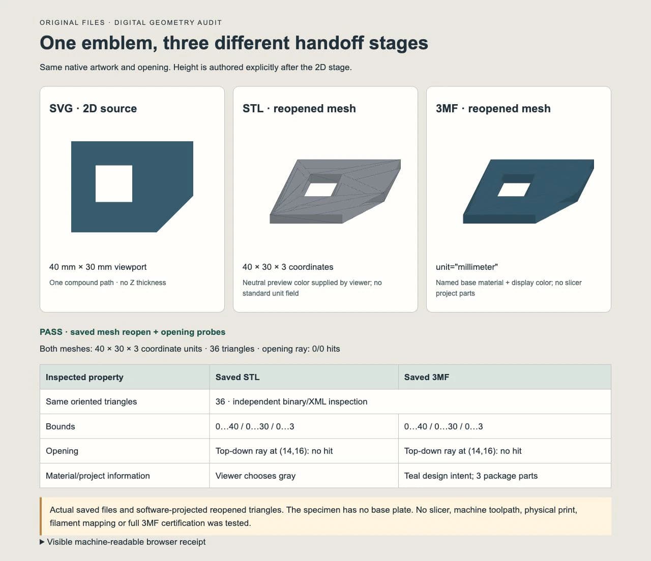
An independent binary/XML inspection found 36 triangles in each mesh and identical oriented triangle coordinates. Both bounds were 0…40 in X, 0…30 in Y, and 0…3 in Z. Every mesh edge had an oppositely directed partner, and the signed volume matched the expected 2,952 cubic coordinate units within a declared 0.000001 tolerance.
The first export failed the edge-direction and volume checks because the opening contour had the wrong winding for our extrusion code. We reversed that contour, regenerated both outputs, and repeated the same checks. Changing the extension would have preserved the faulty mesh.
A separate browser page fetched the saved files through the Three.js STL and 3MF loaders. The declared test was a downward ray through the opening at (14, 16) and another through solid material at (4, 15). The opening ray missed both meshes; the solid ray hit both. These are bounded file and loader checks, not a full conformance certification or a slicer test.
For a browser-based SVG import workflow, the Three.js SVGLoader walkthrough covers a different task: importing paths and checking the scene's shape, orientation, and scale. Our small importer here only handles this fixture's straight contours.
Units travel differently
The SVG declares a physical viewport size as well as a user-space rectangle. A receiving modeler still needs to map that geometry into its own coordinates. Verify a known width after import rather than relying on how large the drawing looks on screen.
Our STL contains a width of 40 in its vertex coordinates. The intended width is 40 mm, but the file has no standard unit field carrying that agreement. If the recipient interprets those numbers differently, the part's size changes even though its triangles remain unchanged.
Our 3MF model explicitly declares:
<model unit="millimeter"
  xmlns="http://schemas.microsoft.com/3dmanufacturing/core/2015/02">
The 3MF Core specification defines that unit attribute and the package's model, resources, and build structure. Still confirm the displayed dimensions in the actual receiving application before proceeding.
A model 3MF and a slicer project carry different information
Our saved 3MF has exactly three ZIP entries:
[Content_Types].xml
_rels/.rels
3D/3dmodel.model
Inside the model, we included one mesh object, one build item, a title, and a named base material with displaycolor="#315D6FFF". The browser loader read the teal display color. There are no slicer project parts in this package.
Core base-material names convey design intent, and displaycolor is a rendering property. The specification explicitly separates it from a promise about the printed material's color. A teal preview does not establish a filament assignment or a successful color print.
A slicer project can include additional application-specific data. Ask the sender whether the file is a geometry exchange or a saved project, and verify the settings that actually reopen. The extension alone cannot answer that question. This comparison did not test a slicer project, printer profile, support layout, or generated machine instructions.
Wrapping the mesh does not add surface detail
The two final mesh files contain the same 36 triangles. Neither gained detail from its extension. Our emblem uses straight edges, so it also avoids a curved-outline approximation comparison. With curved artwork, inspect the tessellation chosen during modeling/export rather than treating a format name as a smoothness setting.
The binary STL was 1,884 bytes; our compressed 3MF was 1,326 bytes. Those sizes describe this small authored example only. Geometry, representation, compression, and included resources affect the result; this is not a universal file-size advantage.
Keep the source SVG and the modeling document when future edits matter. An exported triangle mesh does not preserve the original path-editing or modeling history merely because it can be reopened.
Verify the handoff in the receiving workflow
Before sending a modeled logo, give the recipient its intended width, height, thickness, and file purpose. Then ask them to verify:
- Dimensions: the known width and extrusion height match the intended physical units.
- Opening: the empty region passes through the whole slab rather than ending at a hidden face.
- Orientation and body structure: the emblem faces the intended direction, and any required base or attachment is present.
- Properties: expected object/material information survived; a preview color is not a machine material mapping.
- Production preparation: their actual modeling or slicing workflow completes its own checks and toolpath review.
If an SVG imports without a usable region, follow the SVG extrusion diagnosis. If OpenSCAD is the chosen modeler, use the SVG import and extrusion checklist. Those application questions remain separate from choosing an exchange format.
Where vector recovery belongs
If you already have editable vector artwork, preserve it and work on a modeling copy. If a flat logo exists only as a PNG or JPG, PerfectVector's SVG for 3D printing workflow can create candidate contours for review before modeling. Inspect the silhouette, real openings, unwanted background shapes, and scale in the receiving tool.
That raster-to-vector stage supplies 2D artwork. Height, base plates, tolerances, material assignments, and print preparation still belong to later work. Keep photographs or painted textures as raster references when a flat silhouette would discard the intended result; they may need a different 3D method.
The broader image-to-SVG route for 3D printing covers that earlier source-preparation decision. Our original emblem began as native vector geometry and was not traced or backend-converted.
FAQ
Is SVG a 3D printing file like STL? SVG describes 2D artwork. Software may use its filled boundaries to create a 3D model, but the height and other modeling decisions must be supplied. STL describes an already modeled triangular surface.
Does 3MF always contain printer settings? No. Our inspected 3MF contains model geometry, units, and a base-material display property, with no slicer project parts. Check what the authoring application actually saved and what the recipient can reopen.
Will converting STL to 3MF fix a logo's hole? A package change alone does not repair the source mesh. In our first export, the opening-wall winding needed correction before we regenerated both formats. Inspect the actual geometry after any repair.
Should I send the SVG or the finished mesh to a print service? Ask which stage they will handle. SVG can supply a flat outline if they offer modeling; a supported STL or 3MF can supply a modeled surface. Include intended dimensions and confirm the service's requirements rather than assuming the extension establishes acceptance.
Sources
- W3C — Scalable Vector Graphics 2 — Defines SVG's two-dimensional vector and mixed-content document model.
- Three.js — STLExporter — Documents STL surface geometry, arbitrary units, and binary export.
- Three.js — ExtrudeGeometry — Documents depth, steps, and bevel parameters used in the authored sample.
- 3MF Consortium — Core Specification — Defines model units, package structure, base materials, and display-color limits.
Have only a flat raster logo? Create an SVG candidate for the modeling stage, inspect its boundaries and openings, then choose the mesh or project handoff your recipient actually needs.
More from the blog

Rhino SVG Import: Choose Curves, Hatches, or Surfaces
Choose the right Rhino 8 SVG import option, check object types and holes, and decide when a raster logo needs tracing before you start modeling the design.

Tinkercad SVG Import: Turn 2D Paths Into 3D Shapes
Prepare an SVG for Tinkercad, set its size, and check filled regions, holes, and height. Fix import errors before treating the extrusion as a printable model.