Tinkercad SVG Import: Turn 2D Paths Into 3D Shapes
Prepare an SVG for Tinkercad, set its size, and check filled regions, holes, and height. Fix import errors before treating the extrusion as a printable model.
On this page
To import an SVG into Tinkercad, open a 3D design, choose Import, select the SVG, and review its scale before loading it. Tinkercad turns supported 2D geometry into a solid with a default height. You can then adjust the object in the workspace, as Autodesk explains in Importing 2D designs.
The useful check comes immediately afterward: did the intended material become solid, did the openings stay empty, and are the dimensions correct? A recognizable shape can still have a filled attachment hole or the wrong thickness.
This guide uses a simple key-tag outline to separate file preparation from those 3D checks. The illustration explains the geometry; it is not a tested import or printed sample.
Start with a shape Tinkercad can use
Imagine a rounded rectangular tag with a circular opening near one end. The tag's outer boundary describes the material. The opening describes an area that should remain empty through the tag's thickness.
Choose your source before converting anything:
| Starting file | Useful next step |
|---|---|
| An SVG with editable paths | Inspect the geometry and prepare an import copy |
| A flat PNG or JPG of an original emblem | Vectorize the silhouette, then inspect the resulting paths |
| A simple tag made from rectangles and circles | Draw those shapes directly with dimensions |
| A photograph with shading and texture | Redesign it as a silhouette if a flat extrusion is the goal |
A raster image inside an SVG file still needs conversion into paths. Renaming a PNG does not change its contents. SVG can contain embedded images, but Tinkercad's SVG import and export guide says image data and several appearance features are unsupported. It also lists text among discarded elements, so convert lettering to paths in your editor before importing it.
Keep an editable master and export a separate import copy. Remove the background rectangle, decorative shadows, and objects outside the tag. They have no role in this example's 3D shape.
Check the filled area and the opening
A thick line around a tag and a filled tag can look similar at a glance. They describe different areas. The SVG specification distinguishes fill from stroke: fill paints the interior, while stroke paints along the outline.
For the tag body, prepare a filled outer region with an actual opening. A white circle placed on top of a colored rectangle is still a separate painted object; its color alone does not subtract material. Use your vector editor's subtraction or compound-path tools to build the opening, then inspect the exported copy.
If you want a raised line rather than a filled badge, convert that line's visible stroke into a filled outline first. Inspect the resulting width at the intended physical size. This makes the area you want to extrude explicit.
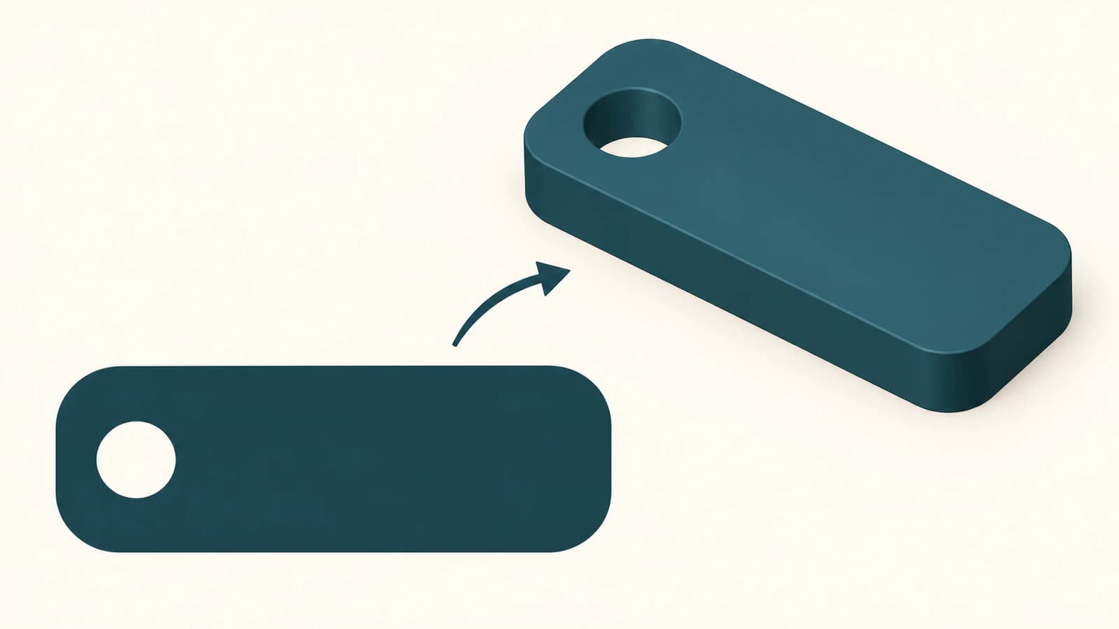
Autodesk's import guide describes closed outer paths becoming solids, with nested profiles alternating between holes and solids. That is the behavior to inspect in this example. More complicated nested shapes deserve their own check; a correct browser rendering does not prove that the imported 3D result matches it.
The circular opening in the SVG is also different from making the entire imported object a Tinkercad Hole. For a tag body, you want the surrounding material to remain solid. Turning the whole object into a Hole changes its role in the model.
Import, measure, then set the height
Use a separate design or an uncluttered area of your project for the first import.
- Open Import in the 3D workspace and select your prepared SVG.
- Review the import scale. Use the intended width and length of the artwork as your reference.
- Load the object and compare its top view with the source silhouette.
- Check the dimensions in the workspace before resizing individual parts.
- Set the extrusion height for your design, then inspect it from an angled view.
The current 2D import help documents scale adjustment before loading, a default solid height, and controls for fill mode and corners in the imported shape's properties. If the tag arrives as a border when you wanted a filled body, inspect both its fill mode and the source geometry. Changing the height will not correct the wrong footprint.
For a scale exercise, suppose the tag is intended to be 50 mm wide but measures 40 mm after import. The proportional correction is 50 / 40 = 1.25. After scaling the whole object, check its other dimensions again, including the attachment opening. These numbers are an example of measurement, not recommended tag or hole dimensions.
If the whole file changes size consistently, the SVG import size diagnosis explains how a reference shape separates a document-scale problem from a distorted part. Avoid changing the outline just to compensate for a scale mismatch.
Height needs its own decision. A recognizable top view says nothing about whether the tag has the thickness your design needs. Likewise, increasing height does not make a narrow neck around the opening wider.
Diagnose an import error before tracing again
Use the symptom to choose the next check. Keep each correction small enough that you can tell whether it helped.
| What you see | Check first |
|---|---|
| No supported elements or an empty import | Whether the file contains actual vector paths rather than an embedded image or live text |
| A solid rectangle instead of the emblem | A background object included in the export |
| The attachment opening is filled | Whether the source contains a real inner opening or a white overlay |
| Only an outline appears | The source fill/stroke construction and imported fill mode |
| The right shape at the wrong size | The overall import scale and a known dimension |
| Extra fragments or rough small details | Stray source objects and unnecessary traced details |
An error message does not prove that the file needs another automatic conversion. First open it in the source editor and isolate one simple filled shape. Export that as a separate SVG and try it. If the simpler file loads, reintroduce the artwork in small parts until the troublesome geometry is identifiable.
Curves need particular care. Autodesk says its importer approximates curves with straight lines. For an SVG that becomes too reduced on import, its suggested repair is converting curves to lines with enough control points to retain the shape. Aggressively deleting nodes can work against that repair. Compare the imported edge with the intended contour rather than chasing a low node count.
For a shape that appears but cannot produce the intended solid, the SVG extrusion troubleshooting guide covers open boundaries, duplicate geometry, and overlapping shapes. Apply the geometry diagnosis while using Tinkercad's own controls; other CAD applications have different sketch workflows.
Where PerfectVector fits
If your only source is a flat PNG or JPG emblem, PerfectVector's SVG preparation workflow for 3D printing can reconstruct editable 2D paths. Inspect the outer silhouette, remove unwanted regions, and check the opening before downloading the SVG for Tinkercad. The conversion gives you geometry to review; it does not choose the tag's physical dimensions or certify a printable model.
A rectangle with a circular opening is usually better drawn directly. Vectorization earns its place when the source has a custom contour you want to recover, such as an illustrated leaf or an original mascot outline. The image vectorization explainer covers that raster-to-path step.
Once the SVG is in Tinkercad, examine the model from above, from the side, and through the opening. Check whether small islands should connect to a base and whether details remain useful at the final size. Continue with the image-to-SVG 3D printing workflow for the later modeling, mesh, and slicer checks. Successful import is one checkpoint in that process.
FAQ
Can Tinkercad import SVG files? Yes. Use Import in a Tinkercad 3D design, choose an SVG containing supported vector geometry, and review the scale before loading it. Inspect the resulting solid, dimensions, openings, and height afterward.
Why does Tinkercad say it cannot find supported elements in my SVG? Check whether the SVG contains an embedded raster image, live text, or appearance features instead of usable paths. Export a simple filled vector shape as a diagnostic copy. Convert lettering to paths and remove unsupported elements before trying the full artwork again.
Why did the hole in my SVG fill in? Inspect how the opening was built. A white shape on top of another shape is not automatically a geometric cutout. Prepare a real inner opening in the source, then check that the imported object preserves it through the full thickness.
Does importing an SVG make it ready for 3D printing? No. You still need to verify physical size, thickness, openings, connected regions, and the later mesh and slicer output. An SVG describes 2D geometry; import creates a model that needs those additional checks.
Sources
- Autodesk Tinkercad — Importing 2D designs — Documents SVG selection, scale, default height, and imported shape properties.
- Autodesk Tinkercad — Import and Export SVG Files in Tinkercad — Explains unsupported SVG content and nested profile behavior.
- Autodesk Tinkercad — SVG is not importing properly — Explains raster exclusion and the importer's approximation of curves.
- W3C — SVG 2 Painting: Filling, Stroking and Marker Symbols — Defines the filled interior, stroked outline, and fill rules for nested paths.
Starting with a raster emblem? Prepare its SVG paths for 3D work, then import the file into Tinkercad and verify the silhouette, opening, dimensions, and height against your design.
More from the blog

Rhino SVG Import: Choose Curves, Hatches, or Surfaces
Choose the right Rhino 8 SVG import option, check object types and holes, and decide when a raster logo needs tracing before you start modeling the design.

OpenSCAD SVG Import: Build a Measured, Extrudable Shape
Import SVG geometry into OpenSCAD, check holes and dimensions, then extrude a measured shape. Learn why a white center may need repair to become a real hole.