How to Vectorize a Floor Plan Without Losing Scale
Turn a scanned floor plan into clean vector lines, calibrate it from one known measurement, and verify the scale before you use the SVG or DXF downstream.
On this page
- What vectorizing a floor plan can—and cannot—preserve
- 1. Preserve the best source and find a known dimension
- 2. Deskew and crop without distorting the plan
- 3. Decide which information belongs in the vector
- 4. Trace the linework and clean the geometry
- 5. Import, measure, and restore the scale
- 6. Verify more than the calibration line
- SVG or DXF for a floor plan?
- When to redraw instead of trace
- FAQ
- Sources
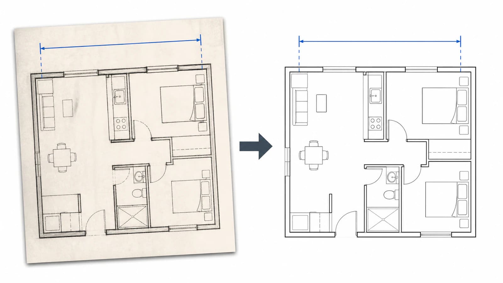
To vectorize a floor plan without losing scale, treat tracing and measurement as two separate jobs. First, clean and trace the visible linework. Then import the vector into the destination app, calibrate it from a dimension you know is correct, and verify at least one other length. The trace preserves geometry; the reference dimension restores scale.
That distinction matters because a PNG, TIFF, or scanned PDF usually does not carry a trustworthy real-world unit. A clean SVG can still open at the wrong physical size, and an accurate-looking trace can still be unsuitable for construction. This workflow is for presentation plans, stencils, and downstream redrawing, not for manufacturing or building from an unverified scan. If the source is a scientific plot or figure rather than a measured plan, use the scientific diagram to SVG workflow, which recovers visible geometry without claiming to restore the data behind it. If the source is a garment pattern, use the scale-safe sewing-pattern workflow to preserve notches, grainlines, and print size.
The scale-safe workflow
- Keep the original scan untouched and identify one reliable printed or measured dimension.
- Deskew and crop the image without stretching it in one direction.
- Trace the structural linework, not paper texture, labels, or scan noise.
- Import the SVG or DXF and measure the known reference line.
- Scale the whole drawing by
intended length / imported length. - Verify another horizontal and vertical dimension before using the file.
What vectorizing a floor plan can—and cannot—preserve
A raster floor plan stores pixels. A vector floor plan stores lines, curves, and filled shapes. Converting the scan can make walls, openings, room boundaries, and symbols much cleaner to resize and edit. It does not automatically recover the drawing's original unit, drafting constraints, wall objects, door types, or surveyed dimensions.
Think of the output as one of three things:
| Intended result | Is an automatic trace enough? | What still needs work |
|---|---|---|
| Presentation graphic or website illustration | Often | Visual cleanup and label replacement |
| Stencil, engraving, or simple CNC reference | Sometimes | Closed paths, tool clearance, scale calibration, and physical verification |
| Editable architectural CAD or construction document | No | Deliberate CAD redraw, constraints, layers, dimensions, and professional verification |
If a dimension controls material, fit, safety, permitting, or construction, do not infer it from a fuzzy line. Return to the source drawing, a verified measurement, or the person responsible for the plan.
1. Preserve the best source and find a known dimension
Work from the original scan or export whenever possible. A screenshot can add resampling, interface chrome, and an unknown zoom level. If the plan came from a multi-page PDF, export the relevant page directly instead of photographing the screen. The National Archives' digitization guidance treats faithful capture and a retained production master as separate concerns from later access copies.
Before editing anything, find a trustworthy reference:
- a printed dimension line whose endpoints are unambiguous;
- a title-block scale, only when you know the scan was not resized;
- a measured feature such as a wall segment or overall room width;
- a reference square intentionally included when the plan was scanned.
A scale bar is useful only if it was scanned with the drawing and has not been cropped or stretched separately. A familiar object—such as a door that “looks standard”—is not a reliable reference. Actual sizes vary, and the line may represent the frame, opening, or swing rather than the dimension you guessed.
Keep a note of the reference endpoints and intended length. You will use the same two points after import.
2. Deskew and crop without distorting the plan
A tilted sheet produces tilted geometry. Rotate the image until long horizontal and vertical walls align with the canvas. Crop away the scanner bed, page shadow, punched holes, and irrelevant margins so the tracer does not turn them into shapes.
Do not correct a skewed scan by independently dragging its width or height until it “looks square.” That non-uniform scaling changes angles and proportions. If the paper is photographed in perspective rather than scanned flat, apply a proper four-corner perspective correction first. Then compare more than one known measurement; a single reference cannot prove that perspective distortion is gone.
For faint archival plans, the preparation principles are similar to preserving line detail in a TIFF scan: separate real ink from paper texture, avoid aggressive thresholding, and inspect small annotations before deciding what to keep.
3. Decide which information belongs in the vector
Trying to trace every mark usually makes the file worse. Separate the plan into information classes:
- Structural linework: wall faces, openings, stairs, fixed outlines, and boundaries you need.
- Symbols: doors, fixtures, electrical marks, and furniture, which may be easier to redraw from reusable vector symbols.
- Text and dimensions: usually better retyped than traced. Traced letters become shapes and remain hard to edit.
- Noise: folds, speckles, stamps, bleed-through, shadows, and halftone texture, which should normally be removed.
Choose the result before tracing. A clean presentation plan might use simplified wall fills and a few labels. A CAD redraw needs meaningful layers and constrained geometry. A stencil or CNC reference needs paths that reflect the actual operation, including closed shapes and cutter-accessible gaps.
This is also where you decide whether you need centerlines or wall outlines. A normal image vectorizer follows visible boundaries. A thick wall line can therefore become a filled shape or two edges, not one architectural centerline. If the destination requires centerlines, rebuild them deliberately in CAD rather than assuming the trace understood the wall.
4. Trace the linework and clean the geometry
For a visual or maker-oriented plan, convert the prepared raster into vector paths, then inspect the result at normal view and high zoom. Look for:
- broken wall segments where faint ink disappeared;
- doubled edges caused by tracing both sides of a thick line;
- small shapes made from dust or compression noise;
- rounded corners where the source should be square;
- labels fused into nearby walls;
- excessive nodes along what should be a straight segment.
Delete noise, join intentional contours, simplify only where the shape remains faithful, and redraw critical straight lines with vector tools. Automatic tracing is a starting point, not a substitute for inspecting every dimension-bearing feature.
PerfectVector can help when the goal is to rebuild a clean scan as editable graphic paths for a presentation, stencil, or visual layer. The prepared raster can be converted through the SVG and DXF workflow for CNC. It does not create an architectural model, recognize semantic wall and door objects, or certify the dimensions. Use CAD for those jobs.
5. Import, measure, and restore the scale
SVG uses a coordinate system and a viewBox; it does not inherently promise that one coordinate equals one millimeter. The SVG coordinate-system specification defines the mapping between user units, the viewport, CSS pixels, and physical units. Different applications can therefore map a file into document units differently, and DXF importers have their own unit assumptions.
After import, measure the exact reference line you recorded earlier. Then calculate:
scale factor = intended length / imported lengthIf a wall should be 4200 mm but imports as 1050 mm, the factor is 4200 / 1050 = 4. Scale the entire vector drawing uniformly by 4. This matches Autodesk's documented reference-scaling method: scale selected objects from a reference length to a specified new length. Do not resize one wall independently, and do not edit the paths merely to compensate for an import-unit mismatch.
The guide to an SVG that imports at the wrong size explains why a correct viewBox can still be interpreted at a surprising physical size. Its known-square test is useful here: it separates a global unit conversion from distorted geometry.
6. Verify more than the calibration line
The reference line proves only that those two endpoints now match. Check at least one other dimension, ideally in the other axis and far from the first reference. Also verify a diagonal or a known room proportion when perspective distortion is possible.
Use this diagnosis:
- Everything differs by the same factor: the geometry is probably proportional, but the import units were wrong. Apply one uniform scale correction.
- Horizontal measurements match but vertical ones do not: the image was stretched or the scan has directional distortion.
- One area matches while distant areas drift: perspective, paper deformation, stitching, or local tracing errors remain.
- Outer dimensions match but openings do not: the trace changed local line positions or you measured different reference edges.
Do not hide a local mismatch by forcing the whole plan to a second dimension. Return to the raster preparation or redraw the affected geometry.
SVG or DXF for a floor plan?
Use SVG when the plan is primarily a graphic: a web illustration, slide, annotated site map, or file you will edit in a design tool. SVG retains visual styling and opens naturally in browsers and vector editors.
Use DXF when the next step is CAD or CAM and the destination handles DXF units and linework more predictably. Even then, importing a traced DXF does not make the drawing dimensionally authoritative. Set the receiving document's units, calibrate from a known length, and inspect the paths.
For cutting or engraving, continue with the image-to-SVG-for-CNC checks: closed profiles, sane node counts, no accidental background rectangle, and no doubled cut lines. Then verify the design against the real stock before generating a toolpath.
When to redraw instead of trace
Redraw the plan in CAD when:
- dimensions must drive construction, fabrication, or fit;
- walls and openings need semantic properties rather than visual outlines;
- the scan is skewed, stretched, incomplete, or too faint to resolve;
- you need reliable area calculations or editable dimension constraints;
- revisions must remain auditable;
- the source includes several inconsistent scales or enlarged details.
Tracing can still help as an underlay. Lock the calibrated vector or raster on a reference layer, then rebuild clean CAD geometry over it. The underlay makes the redraw faster while keeping the final model explicit and measurable.
FAQ
Can I convert a floor plan image to SVG? Yes. A clear scan can be traced into SVG paths for presentation graphics, diagrams, stencils, or a redraw underlay. The result still needs cleanup, scale calibration, and verification; tracing does not turn the scan into an architectural CAD model.
Will vectorizing a floor plan preserve its measurements? It can preserve the drawing's proportions when the scan is undistorted, but it does not preserve a trustworthy physical unit by itself. Calibrate the imported vector from one known dimension and verify other horizontal and vertical measurements.
Should a floor plan be SVG or DXF? Use SVG for visual publishing and design-tool editing. Use DXF when the next application is CAD or CAM and prefers linework exchange. Either format still needs its import units checked and its geometry verified.
How do I calibrate a vector floor plan to scale? Measure a known line after import, divide its intended length by the imported length, and uniformly scale the entire drawing by that factor. Then measure another feature in a different part of the plan to check for distortion.
Can PerfectVector replace a CAD redraw of a floor plan? No. PerfectVector can rebuild suitable scanned linework as editable graphic paths, which can help with presentation plans, stencils, and reference underlays. It does not create constrained CAD geometry, semantic building objects, or verified construction dimensions.
Sources
- W3C — SVG Coordinate Systems, Transformations and Units —
viewBox, viewport mapping, user units, CSS pixels, and physical units. - Autodesk — SCALE command — uniform scaling by factor or by a known reference length.
- Autodesk — Objects are scaled when inserted — insertion-unit mismatches and checking a known dimension after import.
- National Archives — Technical Guidelines for Digitizing Archival Materials — capture, production-master, and quality-control guidance for maps, plans, and paper records.
If the scan is clean and the output is for presentation or a maker workflow, convert the linework to SVG or DXF with PerfectVector, calibrate it from a known dimension, and verify another measurement before using it. When dimensions control the real-world result, use the trace as an underlay and complete the drawing in CAD.
More from the blog

Onshape Image to Sketch: Recover Clean DXF Geometry
An image inserted in Onshape is a tracing reference, not editable sketch geometry. Learn when to trace manually, convert to DXF, and verify scale and paths.

Resize a Rhinestone SVG Without Changing Hole Size
Learn when to restore a rhinestone SVG's import size and when to rebuild its layout. Keep hole diameters fixed, check spacing, and test with your actual stones.