
Convert an Image to SVG With Clean CNC Cut Paths
A CNC follows vector paths, not pixels, so your design has to become a clean SVG or DXF first. Here's how to convert an image into CAM-ready, closed-path vectors.
On this page
- Why a CNC needs a vector, not an image
- Which images cut and carve well, and which don't
- SVG or DXF? What your CAM software wants
- The workflow: from image to CAM-ready vector
- 1. Start from the right source image
- 2. Convert it to clean closed paths
- 3. Separate your colors into operations
- 4. Check the paths before you load CAM
- 5. Import to CAM and assign toolpaths
- What this looks like with PerfectVector
- When converting isn't the right move
- FAQ
- Sources
To convert an image for a CNC profile, pocket, or engraving workflow, trace the design into vector geometry, clean the paths, and import a format your CAM software documents—often SVG or DXF. The CAM application then turns selected geometry into toolpaths. Whether the result cuts correctly depends on the source artwork, the traced paths, physical scale, and the CAM setup.
This guide walks the whole route, from picking the image to assigning toolpaths, for routers and plasma tables alike. The Carbide Create trace-or-import guide compares its built-in Image Trace with a prepared SVG workflow. For CAD reconstruction, the FreeCAD image-to-sketch workflow separates measured native geometry from a decorative DXF handoff. Shaper users can continue with the Shaper Origin-specific size and cut-type checklist before routing. If vector files are new to you, what image vectorization actually does is a quick primer first.
Short on time? The whole workflow
- Check the design suits the operation. Flat, high-contrast art suits profile and pocket tracing; photos and gradients need a raster-engraving, relief, or other workflow.
- Start from your sharpest image, with strong contrast and a clean background.
- Convert it to closed vector paths with an AI vectorizer, and keep your colors separate for cut versus engrave.
- Check the paths: closed shapes, a sane node count, no stray background rectangle, no doubled lines.
- Export SVG or DXF, import to your CAM, scale to the workpiece, and assign profile, pocket, or V-carve toolpaths.
Why a CNC needs a vector, not an image
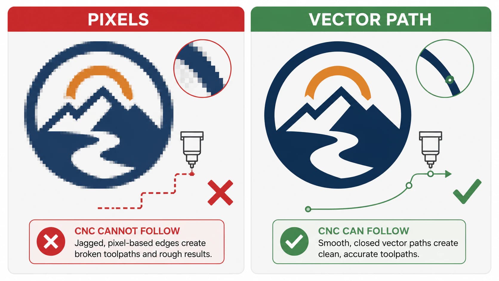
A PNG or JPG is a grid of pixels. For vector-driven profile, pocket, and engraving operations, CAM software works from selected geometry and generates a toolpath—the route the cutter takes. Autodesk’s 2D Profile documentation illustrates this contour-to-toolpath relationship. SVG and DXF can carry the 2D geometry used in these workflows.
That also explains why path quality matters so much here. An auto-tracer that transcribes every pixel edge leaves you with open, broken paths and hundreds of stray nodes, and that is exactly what CAM software rejects: "no closed profiles," jagged curves, a sketch that crawls. On a sheet of aluminum or a nice slab of walnut, a path that breaks at the first corner costs real material. What fixes that is a cleaner file, not a better machine.
Which images cut and carve well, and which don't
What makes a good image for CNC? Flat, high-contrast artwork with clear edges: logos, monograms, lettering, silhouettes, line art, ornaments. These trace into clean closed shapes your CAM can profile, pocket, or V-carve. Photographs, gradient-heavy art, and anything with soft shading do not, because there are no clean edges to trace; you get blobby outlines that mean nothing as a toolpath. The converter tools that advertise "photo to CNC" gloss over this, but the result is the same on every machine.
| Your image | Cut or carve it, or not | Why |
|---|---|---|
| Logo, monogram, lettering | Yes | Clear edges trace into closed shapes for profile or V-carve |
| Silhouette or bold line art | Yes | Single clean outline, ideal for signs and metal art |
| Flat multi-color design | Yes, separate the colors | Each color becomes its own cut or engrave operation |
| Photo or portrait | Usually use another workflow | Raster engraving or a relief workflow preserves tone better than flat tracing |
| Gradient or shaded art | Simplify or use raster engraving | Soft transitions do not map directly to one profile boundary |
| 3D relief look | Use a relief workflow | A flat outline does not encode depth |
If your design lands in a "no" row, the last section covers what to reach for instead. For everything else, on to the conversion.
SVG or DXF? What your CAM software wants
Both formats can carry 2D vector geometry, but their schemas and supported features differ. Choose the format your exact application and version documents, then verify scale and geometry after import. Autodesk Fusion documents inserting SVG into a sketch, while Vectric and SheetCAM document both SVG and DXF imports.
| CAM software | Documented vector import |
|---|---|
| VCarve / Aspire | SVG or DXF |
| Fusion | SVG into a sketch; DXF is also available through its insert/import tools |
| SheetCAM | SVG or DXF |
If your tool accepts both, start with whichever keeps your work simplest. There's a fuller breakdown of the trade-offs in SVG versus DXF for cutting; the short version is that a clean path matters more than the container it ships in.
For SolidWorks, compare the image-to-sketch options before deciding on an SVG or DXF handoff.
The workflow: from image to CAM-ready vector
1. Start from the right source image
The trace can only be as clean as what you feed it. Use the largest, sharpest version of the image you have, with strong contrast between the design and its background. A clean or transparent background keeps the converter from tracing a rectangle around your art, which would otherwise import as an extra profile your CAM tries to cut. Avoid heavily compressed JPGs where you can; their softened edges become wobble that the bit physically follows. More on protecting edge detail in converting without losing quality.
2. Convert it to clean closed paths
Upload the image to a vectorizer and inspect the trace. You can convert your image to CNC-ready vectors and export the supported SVG or DXF result. What you want from this step is specific: continuous boundaries where an enclosed operation needs them, deliberate curves instead of pixel-chasing segments, and no field of speckled fragments. That cleanliness is what decides whether the next steps go smoothly, which is why it gets its own check in step 4.
3. Separate your colors into operations
Each color in a vectorized design can become a separate operation: an outline to profile out, an interior to pocket, lettering to V-carve. Think in operations, then keep those colors apart rather than flattened into one shape. The old manual route for this was painful: reduce colors by hand in a pixel editor, split the design into black-and-white sub-images, trace each one separately, then stack them on layers. A converter that keeps your colors separate on the way out skips that entire grind. The thinking is the same as building a layered file for a cutting machine, just with cut and carve operations instead of vinyl colors.
4. Check the paths before you load CAM
Open the vector (your CAM's preview is fine) and look for four things:
- Closed shapes. An open path has no inside for the software to profile or pocket. This is the most common reason CAM throws "no closed profiles."
- Node count. Hundreds of needless anchor points make the toolpath stutter and the sketch crawl, and they leave faceted curves the bit traces as tiny flats. A clean trace uses far fewer; why traces end up over-noded shows what a sane path looks like.
- No stray background box. If a rectangle got traced around the art, delete it before you generate toolpaths, or the machine will cut it.
- Single lines, not doubled ones. If the trace outlined both sides of a thin stroke, you get two paths a hair apart and the bit cuts the line twice. That double-line problem is worth fixing at the trace, not in CAM.
If the SVG looks reasonable but its DXF export arrives as hundreds of line pieces, diagnose an overloaded DXF before CAM. That check separates source trace density, curve tessellation, duplicate contours, and receiver-specific entity handling.
5. Import to CAM and assign toolpaths
Bring the vector into your software and set up the cut. The menus differ, but the moves are the same:
- Carbide Create, Easel, VCarve / Aspire. Import the SVG, set the real-world size against your stock, and assign operations per shape: profile to cut a shape out, pocket to clear an area, V-carve for sign lettering and fine detail. If you are starting with pixels inside VCarve, the VCarve Trace Bitmap guide covers Threshold, color tracing, Corner Fit, Noise Filter, and the contour audit before toolpaths.
- Fusion. Insert the SVG into a sketch or use a supported DXF workflow, verify its physical size, then create the appropriate 2D toolpath from the intended contour.
- Plasma (SheetCAM and similar). Import the documented SVG or DXF source, configure the operation, and inspect the generated paths. If the art contains enclosed negative space or loose islands, run the plasma-specific bridge and cutability audit before assigning the operation.
Whichever you use, color or layer separation can help organize cut versus engrave geometry. Simulate and inspect the toolpaths, then follow the machine and CAM vendor’s setup and safety procedure before running a job.
Before cutting stock, measure a known feature after import. If every dimension changed by the same factor, use the wrong-size SVG diagnosis to separate unit mapping from path geometry.
If the source is an architectural drawing rather than artwork, follow the floor-plan vectorization and scale-calibration workflow before CAM import. A clean trace does not make an unverified scan dimensionally authoritative.
If your CAD stage is Onshape, first turn the image reference into a usable sketch, then validate the CAM handoff.
What this looks like with PerfectVector
PerfectVector handles the raster-to-vector stage of this workflow. It reconstructs visible regions as editable paths, retains separable color regions for review, and provides supported SVG or DXF output. Inspect the result for continuous contours, redundant fragments, scale, and operation grouping before CAM import.
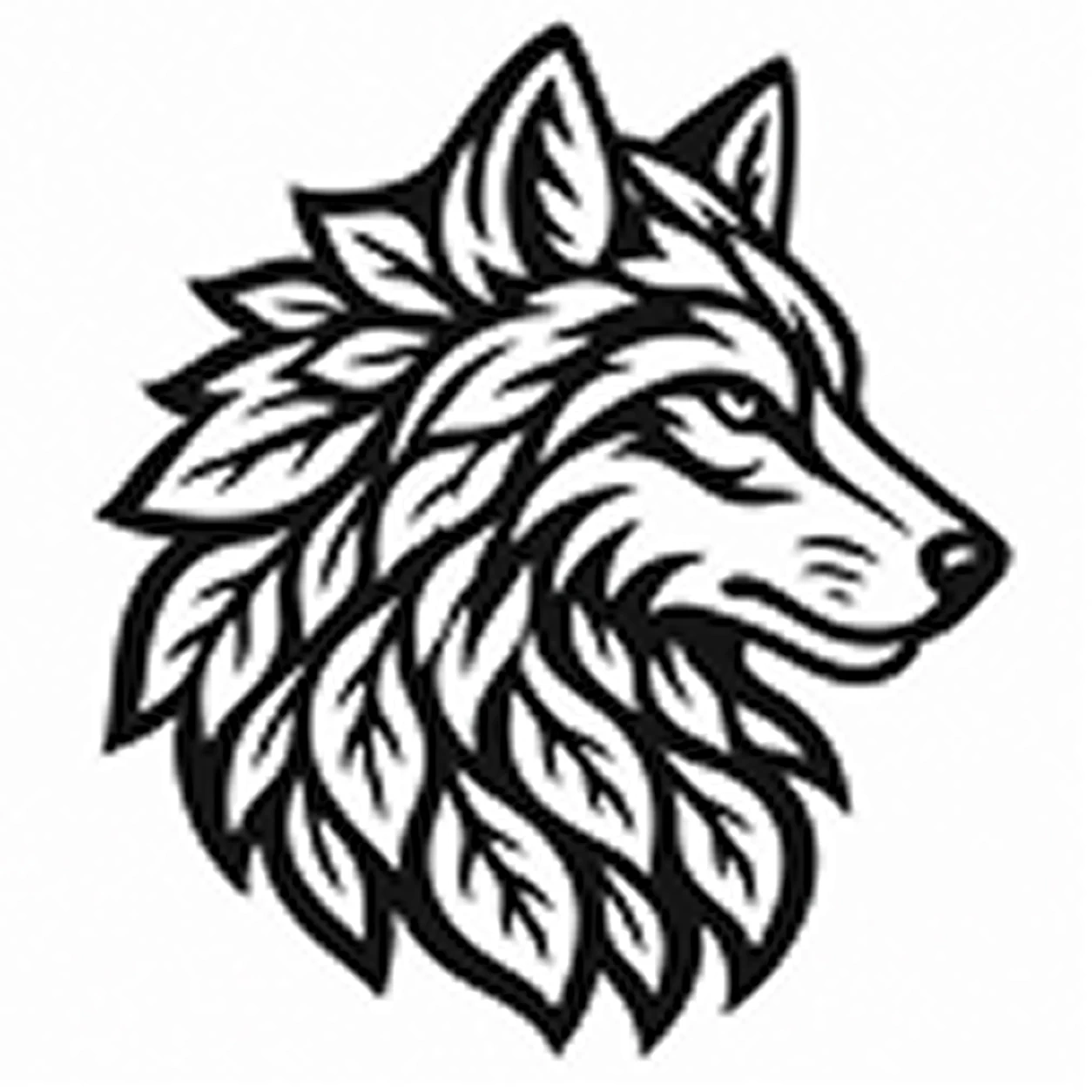
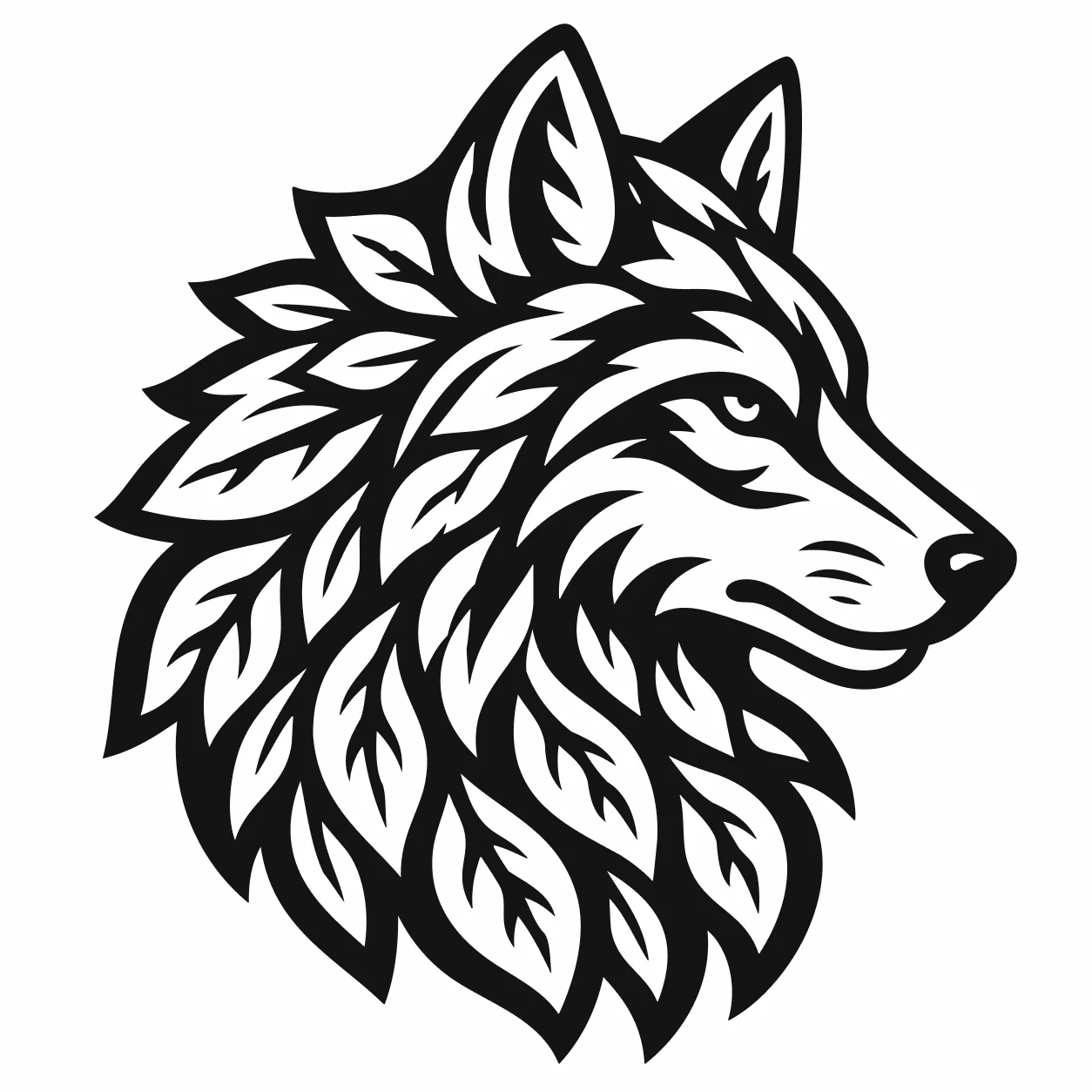
One honest boundary: PerfectVector gives you the clean vector, not the toolpath. It exports DXF or SVG (and PNG, JPG, or PDF if you need them); your CAM software is what assigns operations and generates G-code. A clean closed path is simply what makes that step reliable. Convert an image and export it as DXF or SVG, or start from the general image to vector converter if your project isn't CNC-specific.
When converting isn't the right move
Honesty saves material:
- Photos and portraits are usually better suited to raster engraving, halftone, or relief workflows. Flat vector tracing intentionally discards tonal information.
- Relief and 3D carving require depth information that a flat SVG outline does not provide, so use the workflow documented by the relief/CAM tool.
- Detail finer than your bit won't cut. A 6mm end mill can't follow a 1mm gap, and a V-bit has its own limits. Simplify the design or size the piece up.
- Halftones and stippling are thousands of dots; as paths they're thousands of plunges. Leave those to engraving or rethink the art.
The quick filter: if you could draw the design as flat shapes with a marker, it'll trace and cut. If it only reads with shading and depth, reach for a different process.
FAQ
What image format converts best for CNC? Start from a high-resolution PNG with strong contrast and a clean background. Flat, graphic art like logos, lettering, and line art traces into clean closed paths. Avoid heavily compressed JPGs, whose soft edges add wobble, and avoid photos and gradients, which have no clean edges to trace.
Should I use SVG or DXF for CNC? Both can carry 2D vector geometry, but software support and imported features differ. Vectric and SheetCAM document SVG and DXF import, and Fusion documents SVG insertion into sketches. Use the format your exact workflow supports, then verify dimensions and contours after import.
Why does my CAM software say "no closed profiles"? The traced paths are open, so there's no enclosed shape to profile or pocket. This usually comes from an auto-tracer that left gaps or doubled the lines. Re-convert for closed, low-node paths, and delete any stray rectangle traced around the design before you generate toolpaths.
Can I CNC a photo by converting it to a vector? You can stylize a photo into flat regions, but that does not preserve photographic tone. For a photographic result in material, a raster engraving, halftone, or relief workflow generally fits better than a simple profile trace.
Does converting an image give me a toolpath or G-code? No. Converting gives you clean vector paths as an SVG or DXF. Your CAM software is what turns those paths into toolpaths and G-code, where you set the bit, depths, and feeds. The cleaner the vector, the smoother that step goes.
Sources
- Autodesk Fusion — Insert SVG — Documents importing SVG geometry into a sketch.
- Autodesk Fusion — 2D Profile — Documents selecting contours and generating profile toolpaths.
- Vectric — VCarve User Guide — Lists current vector-file import support and CAM workflow guidance.
- SheetCAM — TNG Manual — Documents SVG and DXF import and toolpath setup.
- PerfectVector — SVG and DXF for CNC — States the current vectorization and export workflow.
Got a design waiting to become a cut? Convert it to CNC-ready vectors, run the path check, and import the SVG or DXF into your CAM to assign toolpaths. A clean closed path is what makes the cut the easy part. (Same image headed for a printer bed instead? The 3D-printing conversion is the sibling workflow.)
More from the blog
Convert an Image to SVG for Clean Laser Cutting
Laser cutters follow paths, not pixels. Here's how to turn a PNG or JPG into a clean, closed-path SVG your machine can cut, and when to engrave instead.
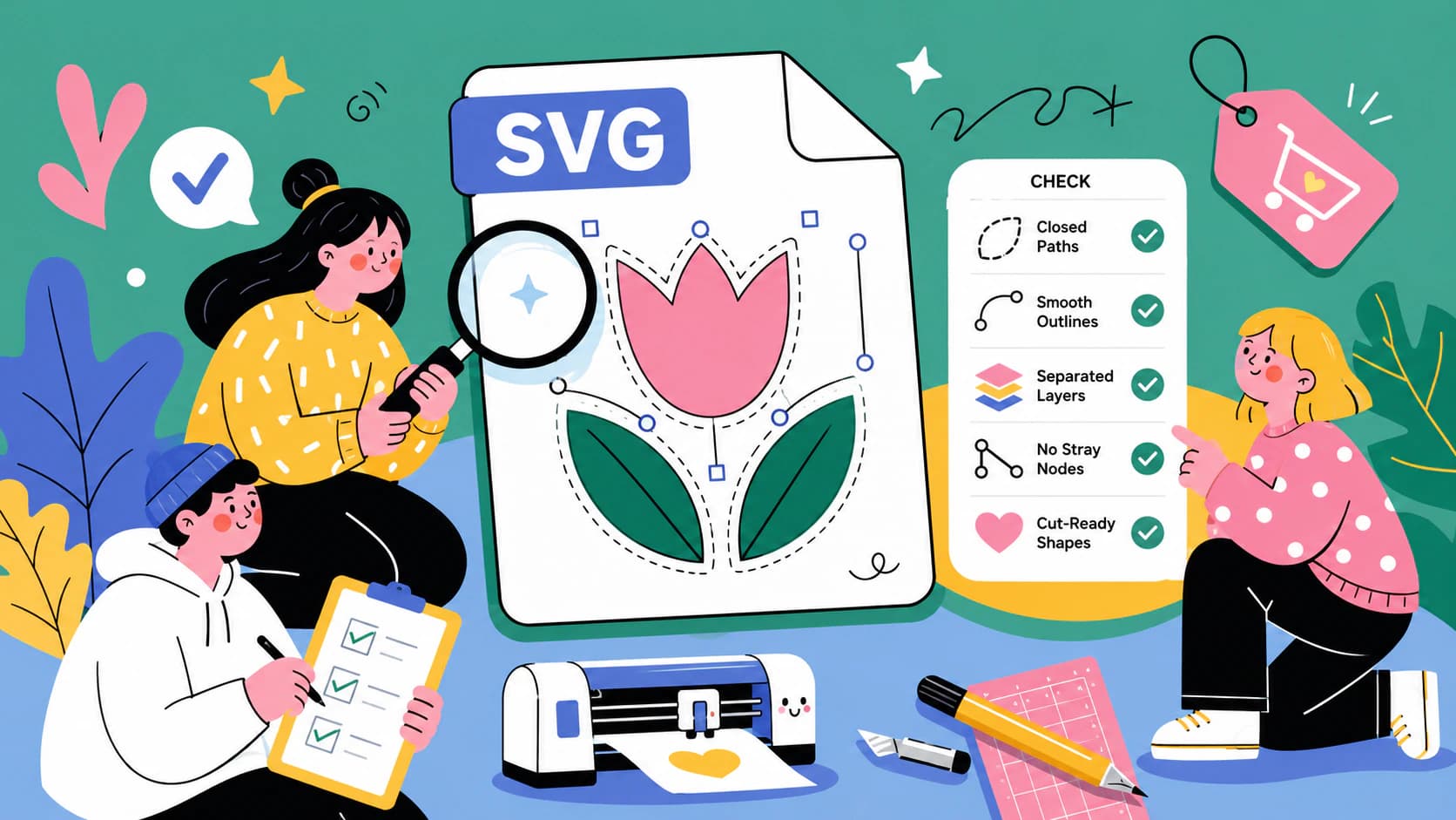
How to Check an SVG File Before You Cut It (or Buy It)
The five-minute preflight for cut files: spot fake vectors, doubled paths, node bloat, and stray boxes before you waste vinyl, plus what to check before buying.