
Turn BMP artwork into DXF contours.
Trace a supported BMP or DIB drawing into outlines you can inspect. Set a physical width for the DXF, then verify dimensions and prepare operations in CAD or CAM.
or try by clicking an image
THE WORKSHOP ARCHIVE
Bring an old bitmap onto the drawing board.
A clean BMP motif can become DXF geometry for a new template or decorative part. Recover the visible outline, then set a known size and check it in the application that will drive the job.
- 01
File condition
Standard uncompressed Windows BMP/DIB is supported. A rejected legacy variant may need a fresh BMP or PNG export.
- 02
Image condition
Inspect scan dust, broken ink and stair-stepped diagonals. Tracing can turn those marks into geometry.
- 03
Drawing condition
Check dimensions after import. Inspect duplicate boundaries and tiny islands before assigning machine operations.
TWO DIFFERENT REVIEWS
Keep the image archive separate from the measurements.
The bitmap records appearance. Your measured specification defines fit.
WHAT THE TRACE RECOVERS
- Visible two-dimensional regions
- Edges represented in the source pixels
- Color-based groups in the DXF
WHAT YOU MUST DEFINE
- Real dimensions and tolerances
- Any required centerline geometry
- Machining operations and material allowance
ACTUAL SAVED PATHS / PNG REFERENCE
Look past the bitmap. Inspect the boundaries.
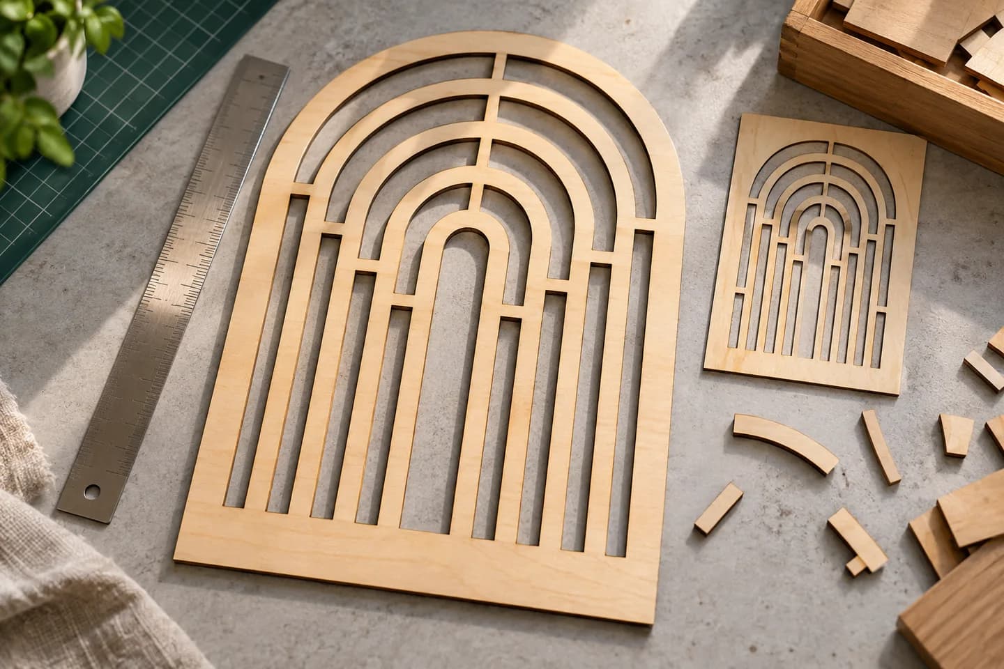
This existing PNG example shows actual traced geometry. It demonstrates what to inspect before DXF export; it is not a BMP conversion result.
Loading the saved paths…
SAVED VECTOR REFERENCE
Inspect real traced boundaries.
This saved PNG conversion shows the geometry behind a decorative panel. Switch to contours and show anchors to see what should be reviewed before a DXF handoff.
FROM IMAGE SPACE TO PHYSICAL SIZE
Choose a width.
Then verify it.
The export width scales the traced artwork. Confirm the dimensions after import, particularly when a template must fit an existing part.
This planning guide does not change your file. Set the intended width again in DXF export after unlocking.
Changing units converts the number. It does not resize the design.
Check contours and dimensions in CAD/CAM.
Set machine operations and toolpaths there.
BMP TO DXF
Choose the source. Review the geometry.
- 01
Upload your BMP
Upload the original BMP or DIB. If its file layout is rejected, export a PNG copy from a compatible image editor first.
- 02
Inspect the free preview
Compare the free preview with the bitmap. Check broken strokes, enclosed spaces and small shapes caused by scan marks.
- 03
Unlock and set export size
Unlock the result with one credit to edit and export. Select DXF, review the Cutting & CAM R12 settings, enter the finished width and choose millimeters or inches.
- 04
Review in CAD or CAM
Download the DXF and verify dimensions and contours in CAD or CAM. Set cutting or engraving operations, toolpaths and allowance for the cut width in that application.
PREPARE THE BMP
Check old bitmap details before tracing.
An uncompressed BMP can still contain scan dust, broken strokes or jagged diagonals. Compare these areas with the traced result.
Trace archived artwork for a CAD drawing.
PerfectVector traces a supported uncompressed BMP or DIB into shapes and exports their boundaries as DXF. Start with a clear logo, motif or bold drawing, then check the trace against the original bitmap.
Use the free, view-only preview to check unwanted outlines, isolated shapes and enclosed spaces. Unlock the result with one credit to edit and export.
The Cutting & CAM profile exports R12 DXF at a width you choose in millimeters or inches, with geometry grouped by color. Verify the dimensions in CAD or CAM. Prepare any centerlines, cut-width allowances, toolpaths and G-code there; the trace does not recover the original measurements.
For an archived mark that only needs resizing and recoloring, BMP to SVG may be the more useful handoff. Choose DXF when the receiving CAD or CAM workflow actually needs outlines.
Good starting points
- Archived monochrome marks and signs
- High-contrast bitmap motifs
- Clean scans of bold artwork
Source checks
- Use a clear original bitmap rather than an enlarged copy of a small icon.
- Check scanned paper, specks and stair-stepped diagonal edges.
- If a legacy BMP is rejected, re-export a copy as a standard uncompressed BMP or PNG in an image editor.
Before manufacturing
- Tiny details, scan marks and jagged edges can produce unwanted contours.
- A thick visible stroke may trace as boundaries on both sides, not a centerline.
- The chosen export width scales the artwork; it does not recover measurements or correct perspective.
Questions before you convert?
Which BMP variants can be converted to DXF?
The converter accepts a supported subset of uncompressed Windows BMP and DIB files, including palette, 16-bit, 24-bit and opaque 32-bit layouts. Compressed variants, unsupported headers and non-opaque 32-bit files need a compatible PNG export from an image editor first.
Can a scanned BMP engineering drawing become accurate CAD?
Tracing recovers visible two-dimensional shapes, not dimensions, constraints or tolerances. Rebuild critical geometry from measurements and verify it in CAD.
Will the BMP resolution set the DXF’s physical size?
Choose the intended width and millimeters or inches in DXF export. Do not treat image resolution metadata as a reliable manufacturing dimension; verify the imported size.
Why do scanned BMP lines have two boundaries?
A thick ink line has area. Region tracing can follow both sides rather than its center. Use a dedicated centerline workflow when the downstream operation needs one line through the stroke.
Can I use a monochrome BMP for a cutting template?
A clear high-contrast motif can be useful. Check closed contours, narrow features and small islands, then use the Cutting & CAM R12 export and verify the geometry in CAD/CAM.
Does BMP-to-DXF produce a finished CNC program?
No. It exports geometry grouped by source color. Set toolpaths, kerf or tool compensation, feeds, speeds and G-code in the appropriate CAM software.
Can I preview the conversion for free?
Vectorizing and viewing the protected preview are free and unlimited. The first unlock of a result costs one credit and enables editing and export. Downloading that same unlocked result again does not use another credit.
Related tools.
BMP → DXF GEOMETRY