Why DXF Files Have Too Many Segments for CNC Work
A DXF gets dense when source traces, exported curves, duplicate paths, or fragments become too many entities. Diagnose the cause, then clean it before CAM.
On this page
- What “too many segments” actually means
- Our source-to-SVG-to-DXF test
- Five reasons a DXF becomes dense
- 1. The trace was already over-detailed
- 2. Curves were tessellated during export
- 3. Duplicate contours overlap
- 4. Tiny fragments became separate objects
- 5. The receiver dislikes a valid entity
- Join, simplify, deduplicate, or redraw?
- A cleanup sequence that preserves intent
- Where PerfectVector fits
- FAQ
- Sources
A DXF has too many segments when a curve reaches it as hundreds of short lines, a trace follows every small source irregularity, duplicate paths overlap, or disconnected fragments become separate entities. The file extension is not the diagnosis. First find whether the density existed before export, appeared during conversion, or only became a problem in the receiving CAM application.
That order matters. Joining 500 segments into one polyline may make the object easier to select, but it still leaves 500 vertices. Converting a clean curve into short lines can create the opposite problem. And deleting points blindly can change the part you meant to cut.
The short diagnosis
- Dense SVG before export: fix the trace or simplify the source master.
- Clean curve becomes many lines after export: change the DXF version or curve-export setting, if the receiving software supports the alternative entity.
- Two identical contours: deduplicate; joining will not remove the second path.
- Hundreds of tiny disconnected objects: remove fragments or rebuild the intended contour.
- Clean file, slow or rejected import: test which DXF entities and layer conventions that exact CAM version accepts.
What “too many segments” actually means
DXF can describe geometry with different entity types. A polyline carries a sequence of vertices; Autodesk's DXF POLYLINE reference documents its following VERTEX records. A spline carries degrees, knots, control points, and related data instead; Autodesk documents those fields in the SPLINE reference.
Those representations are not interchangeable in every receiver. One CAM application may accept a SPLINE directly. Another may flatten it into lines during import. An older controller may prefer arcs and polylines. This is why “keep every curve as a spline” and “export everything as polylines” are both incomplete answers.
The useful question is more specific: how many entities and vertices represent the shape, and does the destination handle them correctly?
Our source-to-SVG-to-DXF test
To isolate source density from exporter behavior, we built five synthetic SVG fixtures of the same general wave shape. One used two native cubic Bézier curves. Three approximated the shape with 16, 64, or 256 straight segments. The last duplicated the 64-segment path exactly.
We exported every fixture at 100 mm through the DXF exporter used in this repository, then counted the emitted POLYLINE, SPLINE, and VERTEX records. We ran the test again and got byte-identical files.
| Source fixture | DXF polylines | DXF splines | DXF vertices | DXF bytes |
|---|---|---|---|---|
| 2 native cubic curves | 0 | 2 | 0 | 1,289 |
| 16 straight segments | 1 | 0 | 16 | 2,900 |
| 64 straight segments | 1 | 0 | 64 | 9,128 |
| 256 straight segments | 1 | 0 | 256 | 34,040 |
| 2 overlapping 64-segment paths | 2 | 0 | 128 | 17,650 |
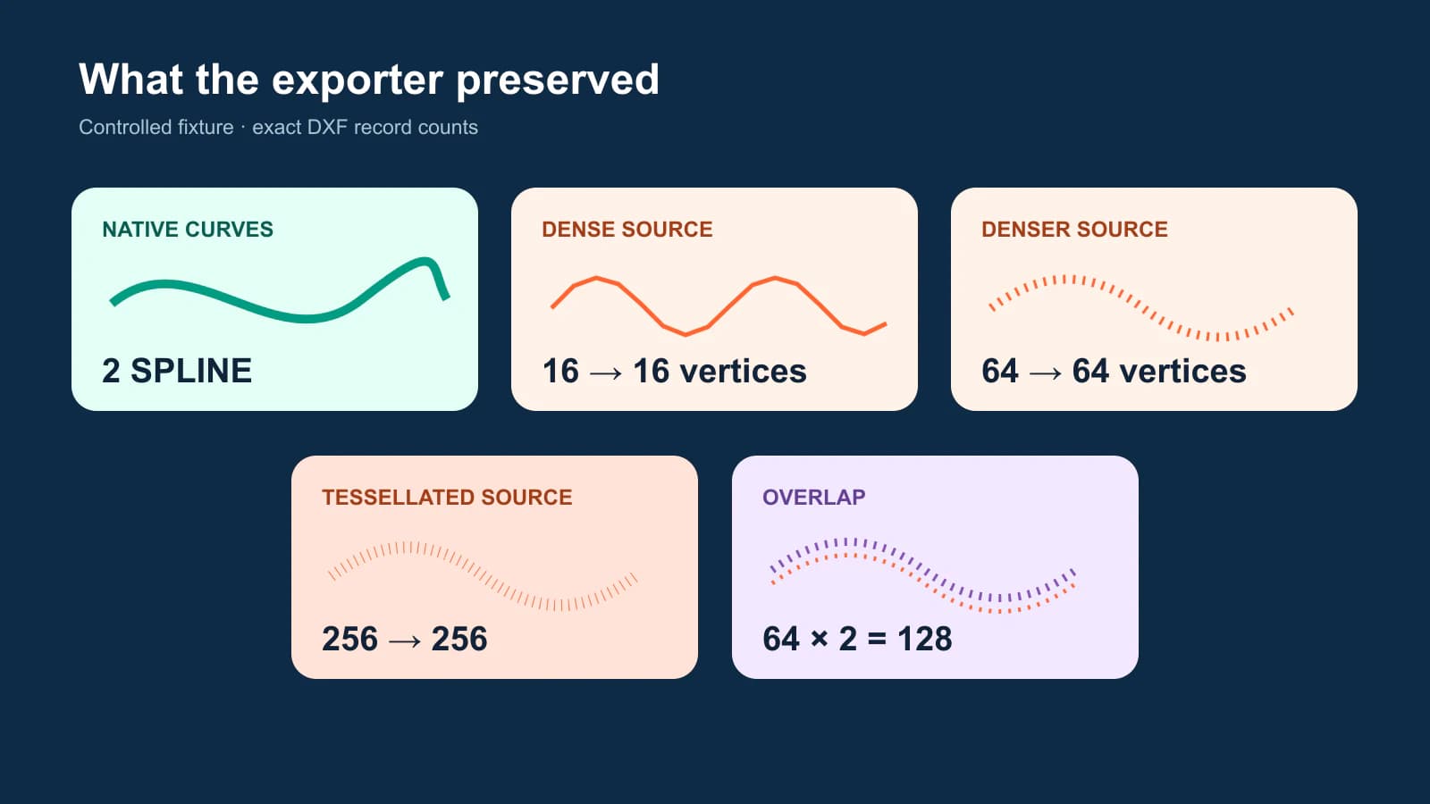
The result is narrow but useful: this exporter did not invent extra straight segments for these fixtures. It preserved the source representation. The native curves stayed native; the dense lines stayed dense; the duplicate stayed duplicated.
Do not treat the numbers as a universal benchmark. They do not measure every converter, every DXF version, every CAM importer, or a typical PerfectVector trace. They demonstrate a diagnostic method you can repeat with your own file.
Five reasons a DXF becomes dense
1. The trace was already over-detailed
An image trace can place points along compression noise, antialiased edges, scan texture, or tiny bumps that have no production value. Exporting that SVG to DXF only changes the container if the exporter preserves the path.
Inspect the vector master before conversion. If a simple arc already looks like a chain of points, start with the SVG node-count diagnosis. Fixing the source is safer than asking CAM to repair it later.
2. Curves were tessellated during export
SVG paths can contain line, cubic Bézier, quadratic Bézier, and arc commands; the W3C path specification defines those commands. A DXF exporter must map them to entities the selected DXF version and destination can read. Some workflows preserve a curve as SPLINE or ARC. Others approximate it with short straight segments.
If the SVG has a clean curve but the DXF shows a dense polyline, compare export settings and versions. Use the least destructive representation the receiver reliably supports, then verify the imported curve at high zoom and against a known dimension.
3. Duplicate contours overlap
A duplicate can be invisible on screen. It becomes obvious only when the CAM preview selects two contours, cuts an edge twice, or reports twice the expected entity count.
Our duplicate fixture did exactly what it should: two 64-segment paths became two polylines with 128 total vertices. Joining each contour would still leave both. Deduplication is the fix.
4. Tiny fragments became separate objects
Specks in a raster, gaps in a scan, or a failed join can produce many short paths. A CAM importer may treat every fragment as a contour, selection object, or separate operation candidate. Delete fragments that do not belong, but inspect them first; a short line can also be an intentional detail.
5. The receiver dislikes a valid entity
A DXF can be structurally valid and still be a poor handoff for one machine workflow. SendCutSend notes that dense nodes may come from third-party converters or splines broken into line segments and recommends checking the source and software-specific curve settings in its dense-node guidance.
Test the destination, not just a desktop preview. If a SPLINE fails but an ARC works, rebuild a true arc. If the application requires polylines, choose a documented tolerance and measure the result. The receiver decides which representation is practical.
Join, simplify, deduplicate, or redraw?
These commands solve different problems:
| Action | What it changes | Use it when | Main risk |
|---|---|---|---|
| Join | Connects endpoints into a longer object | Correct pieces belong to one continuous contour | Keeps the same excessive vertices |
| Simplify | Removes or refits points within a tolerance | A curve has redundant points | Changes corners, radii, holes, or fit |
| Deduplicate | Removes coincident copies | The same contour exists twice | Deletes intentional parallel geometry if tolerance is too broad |
| Redraw as arc/spline | Replaces faceted geometry with a native curve | The design is truly circular or smoothly parametric | A guessed curve may not match the intended part |
For decorative signs, controlled simplification may be enough. For a bearing seat, mating profile, gasket, or dimensioned mechanical part, do not infer geometry from a noisy trace. Rebuild it in CAD from the required dimensions.
A cleanup sequence that preserves intent
- Save an untouched master. Work on a copy so every cleanup step is reversible.
- Inspect before DXF export. In the SVG or design source, zoom into simple curves and count suspicious nodes. Look for duplicates, open endpoints, and specks.
- Export one test curve. A single circle, arc, or Bézier curve tells you how the exporter and receiver negotiate entity types without the noise of the full drawing.
- Count by type. Record LINE, ARC, POLYLINE/VERTEX, and SPLINE entities before and after import if the tools expose them.
- Apply one repair at a time. Deduplicate first, remove fragments second, join intended pieces, then simplify or redraw only where needed.
- Verify geometry. Measure a known length, check closed profiles, and compare the cleaned curve against the untouched master.
- Generate a toolpath preview. Confirm the intended contour is selected once, direction and compensation are correct, and no tiny moves appear unexpectedly.
If you are starting from a PNG or JPG rather than an existing vector, follow the broader image-to-SVG for CNC workflow before this DXF audit. If Onshape is the receiver, use the Onshape image-to-sketch DXF handoff to choose between manual reconstruction and traced geometry. If you are deciding which container to hand off, SVG versus DXF for cutting covers compatibility and units.
If you use QCAD, the Trace Bitmap contour and centerline guide helps you decide whether a traced perimeter or deliberately drawn CAD geometry should enter this DXF audit.
For a trace made inside CAM, use the VCarve Trace Bitmap contour audit or the Carbide Create trace-or-import guide before assigning toolpaths. Both routes still need a check for open contours, fragments, and unnecessary nodes in the receiving workspace.
Where PerfectVector fits
PerfectVector can turn a raster source into a vector and provide a DXF candidate, which is useful when you do not have a vector master to clean. It does not know your machine tolerance, intended dimensions, bit, controller, or CAM import rules. Those remain your production checks.
Convert the original image to DXF, then inspect the result rather than accepting the extension as proof. Check simple curves for dense vertices, remove unintended fragments or duplicates, measure a known feature, and preview the toolpath in the destination software. If the artwork is actually dimensioned engineering geometry, redraw it in CAD instead of treating an image trace as authoritative.
FAQ
Why does my DXF have thousands of segments? The source may already contain a dense trace, the exporter may have flattened curves into short lines, duplicate paths may overlap, or tiny fragments may have become separate entities. Compare the source and DXF counts before deciding which cause applies.
Does joining DXF segments reduce the node count? Usually not. Joining connects pieces into a longer polyline, which can help contour selection, but it generally preserves the vertices. Use simplify or refit for redundant points, deduplicate for overlapping copies, and redraw true arcs or splines when the geometry warrants it.
How many segments are too many for CNC? There is no universal threshold. The acceptable count depends on shape complexity, tolerance, CAM software, controller, and operation. A simple circle made of hundreds of tiny lines deserves investigation; a detailed ornamental contour may legitimately need more geometry.
Should I export DXF curves as splines or polylines? Use the entity type your receiving software documents and handles reliably. Splines can preserve compact smooth geometry, while some older or specialized workflows prefer arcs or polylines. Test one curve, inspect the import, and verify dimensions before converting the full file.
Can I reduce DXF nodes without changing the cut? Only within a tolerance, and the tolerance must come from the job. Simplification can move edges, soften corners, and change fitted features. Compare the cleaned geometry with the master and measure critical dimensions; redraw mechanical geometry in CAD when exactness matters.
Sources
- W3C — SVG Paths — Normative definition of SVG path commands and curve representations.
- Autodesk — POLYLINE DXF reference — Primary reference for polyline structure and following vertex records.
- Autodesk — SPLINE DXF reference — Primary reference for spline degree, knots, weights, and control points.
- SendCutSend — Preventing dense nodes — Receiver-side guidance on converters, broken-down splines, and curve cleanup.
A good DXF is not the one with the fewest possible entities. It is the one that preserves the intended geometry in a form the receiver can use. If your only source is an image, make a DXF candidate with PerfectVector, run the entity and dimension checks above, and reject or repair it before CAM when the evidence says you should.
More from the blog

Convert an Image to SVG for CNC Plasma Cutting
Convert an image to SVG for CNC plasma cutting, then check islands, bridges, closed contours, small features, and CAM settings before the first test cut.

FreeCAD Image to Sketch: Build Editable Geometry
Choose the right FreeCAD image-to-sketch workflow: trace a scaled reference for exact CAD work, or convert suitable flat artwork to DXF and clean it up.