Onshape Image to Sketch: Recover Clean DXF Geometry
An image inserted in Onshape is a tracing reference, not editable sketch geometry. Learn when to trace manually, convert to DXF, and verify scale and paths.
On this page
- What Onshape inserts from an image
- Manual trace or DXF conversion?
- Route 1: trace the image inside Onshape
- Route 2: convert the image to DXF, then insert it
- 1. Clean the raster source
- 2. Build a reviewable DXF candidate
- 3. Inspect before you import
- 4. Insert the DXF into an empty Onshape sketch
- 5. Verify scale and topology
- 6. Replace critical traced features
- Common failures after DXF import
- Where PerfectVector fits, and where it does not
- FAQ
- Sources
In Onshape, inserting a PNG or JPG gives you a picture to sketch over. It does not turn the visible edges into editable sketch curves. Onshape's current Insert Image help describes the image as a basis and guide for creating sketch geometry.
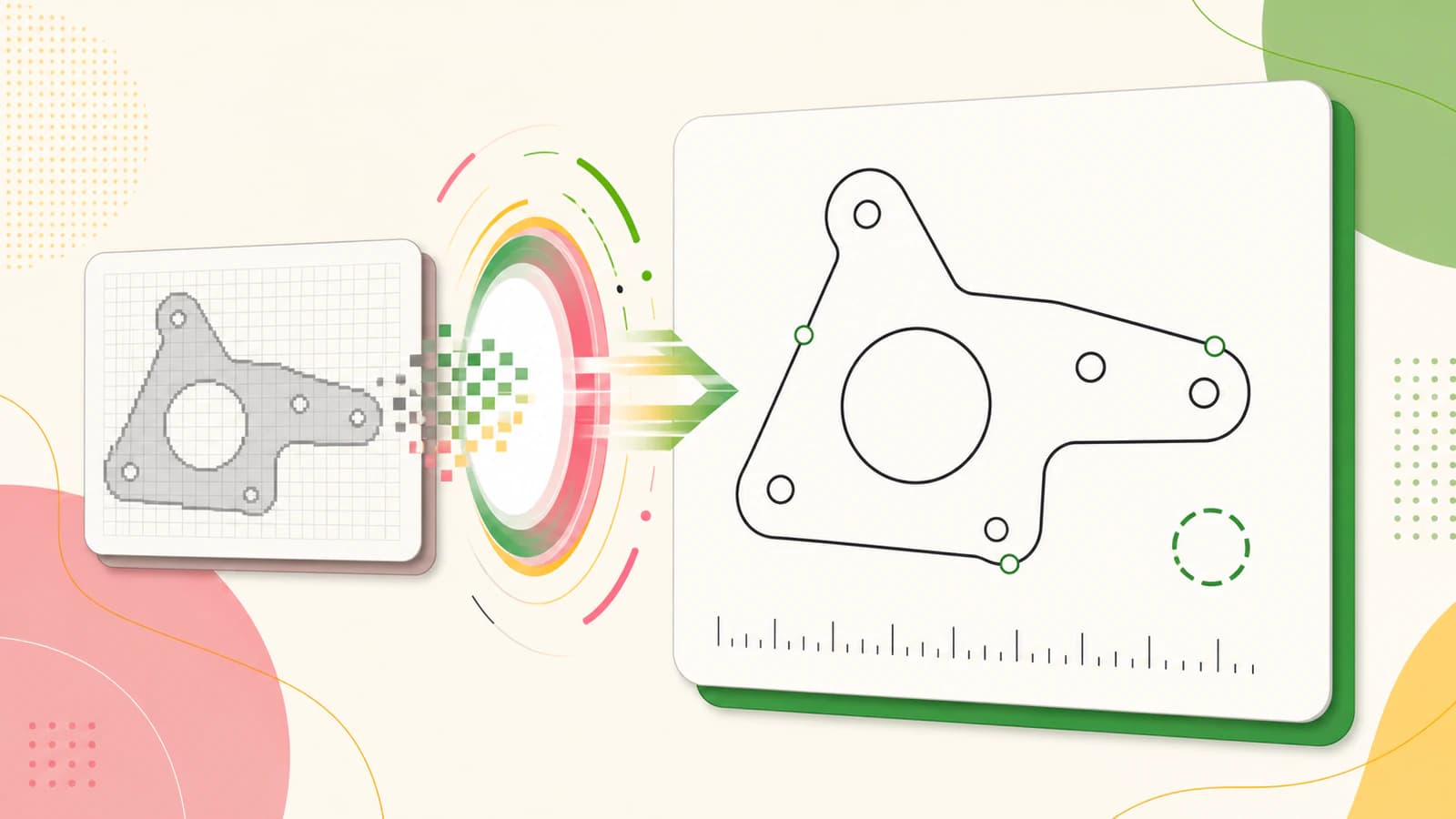
You therefore have two practical routes. Trace and constrain the important features inside Onshape when the part must follow known dimensions. For suitable flat artwork, convert the raster to vector paths, export DXF, and insert that file as sketch entities. Either way, measure the result before using it to make a feature.
Choose the route before you trace
- Dimension-controlled part: use the picture as a reference, then rebuild lines, arcs, circles, and constraints in Onshape.
- Logo, silhouette, badge, stencil, or decorative profile: a raster-to-DXF trace can save time, provided you inspect the paths.
- Photo, gradient, shadow, or textured drawing: simplify the source or redraw the intended boundary. Automatic tracing will follow visible contrast, not design intent.
- Existing SVG or CAD file: use that vector source instead of tracing a screenshot of it.
What Onshape inserts from an image
The Insert Image command accepts PNG, JPEG, GIF, and BMP files, according to the current Onshape documentation. The picture sits in a sketch as a reference. You can position it, then create normal Onshape geometry over it.
That distinction explains the common surprise: a visible outline is not automatically selectable as a line or face. The pixels tell you what the object looks like. They do not contain endpoints, radii, constraints, or closed sketch loops.
| What you insert | What Onshape receives | Best use | Main check |
|---|---|---|---|
| PNG, JPG, GIF, or BMP | A reference image | Manual reconstruction from a drawing or photo | Calibrate it before tracing |
| DXF or DWG | Sketch entities | Reusing or tracing suitable vector geometry | Units, closure, duplicates, and density |
| Native sketch geometry | Lines, arcs, circles, splines, dimensions, and constraints | Exact mechanical intent | Constraint state and dimensions |
Onshape's official image-sketch Tech Tip adds a useful detail: the first dimension you apply to sketch geometry also scales the image. That is convenient for setting a reference, but the picture is still not a dimensioned model.
Manual trace or DXF conversion?
Use the geometry's purpose as the deciding factor, not the number of visible edges.
Trace manually in Onshape when a hole must be a real circle, a corner needs a specified radius, two faces must mate, or a dimension controls whether the part works. A noisy picture cannot tell you the authoritative diameter or tolerance. Rebuild those features from measurements, a drawing, or the original design data.
Convert to DXF first when the boundary itself is the useful information. A flat logo, sign profile, stencil, decorative panel, or laser-cut silhouette can be a good candidate. Even then, treat the trace as a draft. Check scale, path closure, duplicate contours, tiny fragments, and excessive points.
There is also a useful middle ground. Import the image, sketch only the few critical circles and datums in Onshape, and use converted artwork only for the decorative boundary. This keeps engineering intent separate from traced appearance.
Route 1: trace the image inside Onshape
This route takes longer, but it gives you control over what every entity means.
- Start from the best source you can get. Use an orthographic image rather than a perspective photo. Crop away the desk, shadows, labels, and unrelated objects.
- Add a scale reference. A known overall width, hole spacing, or printed ruler is better than guessing. Make sure it lies in the same plane as the part.
- Import the image into the document. Create or edit a sketch, choose Insert Image, and place the source on the sketch plane.
- Calibrate before tracing details. Draw a line between two known points and apply the known dimension. Onshape's Tech Tip explains that the first sketch dimension scales the image.
- Rebuild simple geometry as simple geometry. Use circles for holes, arcs for constant radii, and straight lines where the edge is straight. Do not approximate a circle with dozens of short segments just because the pixels are rough.
- Constrain and dimension the sketch. Coincident, tangent, horizontal, vertical, and symmetry constraints carry design intent that an image trace cannot recover.
- Hide the image and inspect the sketch alone. Look for gaps, doubled entities, accidental kinks, and features that only appeared to align because the picture was still visible.
For a mechanical part, this is usually the safer route. The image helps you interpret the shape, while dimensions and constraints define the part.
Route 2: convert the image to DXF, then insert it
This route is faster when the source is artwork rather than a dimensioned component.
1. Clean the raster source
Use the highest-resolution original, not a screenshot of a compressed preview. Remove the background if it is not part of the shape. Flatten soft shadows and gradients into deliberate regions, or omit them. A clean silhouette gives a tracer a much clearer boundary than a photograph.
If the job will eventually go to a router, laser, or plasma workflow, the broader image-to-SVG for CNC guide explains how source noise becomes cut-path noise.
2. Build a reviewable DXF candidate
For suitable flat artwork, convert the image to DXF with PerfectVector. The tool rebuilds visible artwork as vector paths, lets you review the vector result, and can export a Cutting & CAM R13 DXF at a physical width you choose in millimeters or inches. It can also organize geometry into layers by source color.
This is a geometry handoff, not CAD reconstruction. The file does not contain your intended radii, tolerances, constraints, G-code, feeds, speeds, kerf, tabs, or toolpath. Those choices remain in Onshape and the downstream CAM workflow.
3. Inspect before you import
Check the vector result at high zoom. A simple curve should not look like a saw edge or a long chain of unnecessary nodes. Confirm that intended holes remain holes, separate regions have not merged, and small specks did not become separate contours.
If the DXF contains hundreds of short entities for a simple curve, use the DXF segment-density diagnosis before bringing that complexity into a sketch.
4. Insert the DXF into an empty Onshape sketch
Import the DXF into the Onshape document first. Then create a new empty sketch and use Insert DXF or DWG to place it. Onshape's current DXF/DWG help says the imported file is inserted as sketch entities and recommends an empty sketch, although insertion into an existing sketch is possible.
Keeping the import separate makes diagnosis easier. You can suppress, replace, or compare the traced geometry without mixing it with dimensions and features you have already built.
5. Verify scale and topology
Measure one known width as soon as the entities appear. If the number is wrong, check the physical width and units used during export and import. Do not keep stretching a sketch by eye. The SVG wrong-size guide covers the same source-versus-receiver unit problem in more detail.
Next, test the profiles you expect to use. A closed region should select as a coherent face for an extrude or related feature. Zoom into corners and junctions if it does not. Look for open endpoints, overlapping copies, self-intersections, and tiny isolated paths.
6. Replace critical traced features
Keep decorative contours that survive inspection. Replace critical holes with dimensioned circles, straight edges with constrained lines, and known radii with proper arcs. The goal is not to preserve every point the tracer produced. It is to create the simplest sketch that represents the intended result.
Common failures after DXF import
| Symptom | Likely cause | What to do |
|---|---|---|
| The imported sketch is much too large or small | Export width or import units do not match | Re-export at a known physical width, reimport, and measure immediately |
| A region will not form a selectable profile | Gap, overlap, self-intersection, or duplicated edge | Inspect endpoints and corners; repair only the failing contour |
| Curves look faceted | The trace or DXF export used many short straight segments | Simplify within a known tolerance or redraw true arcs and circles |
| The sketch solves or edits slowly | Too many entities or tiny fragments | Remove irrelevant details and rebuild simple geometry natively |
| Holes are slightly oval or uneven | Perspective, lens distortion, or noisy pixels | Replace them with dimensioned circles from known centers and diameters |
| The cut would follow both sides of a thick stroke | The tracer outlined the stroke instead of recovering a centerline | Choose the intended boundary or redraw the centerline for the operation |
Do not judge the file only by how it looks in the viewport. A clean preview can still hide duplicates or an open endpoint. Selection behavior, dimensions, entity inspection, and the eventual CAM preview are better evidence.
Where PerfectVector fits, and where it does not
PerfectVector is useful when a clean flat raster is the best source you have and an editable outline is the next practical step. It can shorten the artwork-to-DXF portion of the workflow. It cannot infer a missing engineering drawing from a photograph.
Good candidates include logos, bold silhouettes, badges, stencils, and flat illustrations. Poor candidates include shaded product photos, reflective parts, perspective views, blurred scans, and geometry whose function depends on exact fits. When the source is poor, better tracing can still produce a precise description of the wrong edge.
The final responsibility is the same for manual and automatic routes: define the intended size, inspect the paths, rebuild critical features, and test the receiving workflow.
FAQ
Can Onshape automatically convert an image into a sketch? Onshape's current Insert Image documentation describes the image as a basis and guide for sketch geometry, not as automatically generated sketch curves. Trace it manually for dimension-controlled work, or convert suitable flat artwork to DXF outside Onshape and insert the DXF as sketch entities.
How do I scale an imported image in Onshape? Place the image in a sketch, draw geometry between two points whose real distance you know, and apply that dimension. Onshape's official Tech Tip says the first sketch dimension scales the image. Verify another known distance before relying on the reference.
Can I import SVG directly into an Onshape sketch? For the workflow covered here, use a DXF or DWG that Onshape can insert as sketch entities. If your source is SVG, export a receiver-compatible DXF, set a known physical width, then verify the size and contours after import.
Why does my traced DXF fail to make a closed Onshape profile? The contour may have a small gap, overlapping segments, a self-intersection, or duplicate geometry. Inspect the failing boundary at high zoom, repair the specific endpoints or overlaps, and replace simple critical features with native lines, arcs, or circles.
Sources
- Onshape Help — Insert Image — Current documentation for supported image types and using an image as a sketch guide.
- Onshape Resource Center — How to Start a Sketch with an Imported Image — Official workflow for positioning, scaling, and sketching over an image.
- Onshape Help — Insert DXF or DWG — Current documentation for inserting imported DXF/DWG files as sketch entities.
- PerfectVector — Image to DXF Converter — First-party description of path reconstruction, physical-width export, layer grouping, and output limits.
If the source is flat artwork rather than dimensioned engineering geometry, make a DXF candidate with PerfectVector, insert it into a new Onshape sketch, and measure and inspect the paths before building a feature.
More from the blog

FreeCAD Image to Sketch: Build Editable Geometry
Choose the right FreeCAD image-to-sketch workflow: trace a scaled reference for exact CAD work, or convert suitable flat artwork to DXF and clean it up.

SolidWorks Image to Sketch: Choose the Right Route
Turn a SolidWorks Sketch Picture into useful geometry with Picture to Sketch, AutoTrace, manual reconstruction, or a DXF handoff, then verify the result.