FreeCAD Image to Sketch: Build Editable Geometry
Choose the right FreeCAD image-to-sketch workflow: trace a scaled reference for exact CAD work, or convert suitable flat artwork to DXF and clean it up.
On this page
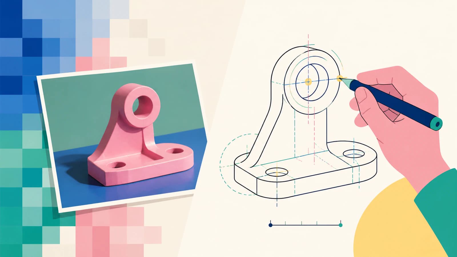
FreeCAD can place an image on a plane, but that image is still a reference. It does not become constrained sketch geometry by itself. To get an editable sketch, either trace the reference with native lines, arcs, and circles, or convert suitable flat artwork to vector paths and bring those paths into a CAD workflow.
The right route depends less on speed than on what the geometry means. A dimensioned bracket should be rebuilt from measurements. A decorative silhouette or logo can be a sensible tracing candidate.
Choose the route before you trace
- Dimension-controlled part: insert the image as a reference, calibrate it, and redraw the geometry with constraints.
- Flat decorative artwork: create a DXF candidate, import it, and inspect every contour before using it.
- Perspective photo: do not trust a direct outline for fit-critical work. Lens and perspective distortion move the apparent edges.
- Single-stroke drawing: ordinary fill tracing outlines both sides of each stroke. Use a centerline workflow if one toolpath is required.
What an imported image gives you
FreeCAD's Image Workbench documentation describes placing raster images on planes. That is useful for visual reference, proportion, and manual reconstruction, but pixels have no dimensional constraints, tangent relationships, or editable radii.
Treat the image as evidence, not geometry. Before drawing, ask which distances are known, whether the camera was square to the part, and which features must remain exact. If all you have is a photo, one known measurement can establish an approximate scale, but it cannot remove perspective distortion.
Route 1: redraw a dimension-controlled part
This is the slower route and usually the safer one for mechanical work.
- Crop the image around the object and correct obvious rotation before importing it.
- Place the image on the plane that best matches the photographed face.
- Scale the reference from a known distance, not from the viewport.
- Build the largest straight edges and centerlines first.
- Add circles and arcs as native geometry, then apply dimensions and constraints.
- Check a second known measurement. If it misses, the reference is distorted or the first calibration was wrong.
Do not follow every pixel wobble. A hole that appears slightly oval in a photo is more likely to be a circle seen at an angle than a carefully designed ellipse. Reconstruct the intended feature from measurements and design logic.
Route 2: use a vector or DXF handoff
A raster-to-vector handoff makes sense for flat, high-contrast artwork: signs, badges, stencils, gaskets without tight tolerances, and decorative profiles. The broader image-to-SVG workflow for CNC follows the same boundary: trace decorative geometry, but rebuild dimension-critical features from measurements. It is not a shortcut to an engineering drawing.
For a suitable source, convert the image to DXF with PerfectVector. Set a known physical width, download the Cutting & CAM R13 DXF, then open or import it in the FreeCAD workflow you plan to use. The conversion rebuilds visible boundaries as paths. It does not know which holes, radii, or clearances are functionally important.
Audit the imported geometry
A successful import is only the start. Check the geometry as if it came from an outside supplier:
- Measure the overall width and one internal feature. This catches unit and scaling errors early.
- Look for closed contours. Tiny gaps and self-intersections can prevent faces, pockets, or profiles from forming.
- Delete duplicate paths. Stacked copies may look normal but create ambiguous or repeated operations downstream.
- Inspect node density. Hundreds of short segments around a simple curve make editing harder and can produce rough machine motion.
- Replace critical features. Redraw holes as dimensioned circles and straight edges as constrained lines.
If the trace is visually close but structurally messy, rebuilding a few key features is usually faster than trying to preserve every imported segment.
Which images convert well?
Clean silhouettes, solid-color logos, and high-contrast scans are good candidates. Shaded product photos, reflections, textured backgrounds, and low-resolution screenshots are not. Better tracing can describe a poor edge more neatly, but it cannot discover the intended dimension behind that edge.
For a photographed part, keep the image as a reference and redraw. For flat artwork, vectorization can remove repetitive outlining work. That boundary is what keeps a quick workflow from becoming false precision.
FAQ
Can FreeCAD automatically convert an image into a sketch? Not as a general one-click engineering reconstruction. An imported image is a raster reference. You can trace it manually with constrained sketch geometry, or convert suitable flat artwork to vector paths and import those paths for cleanup.
How do I scale an image accurately in FreeCAD? Use a distance that is known in the real object, calibrate the reference to that distance, and verify a second measurement. A single dimension sets scale but does not correct perspective or lens distortion.
Should I use SVG or DXF for a FreeCAD sketch workflow? DXF is the more direct handoff when the goal is CAD-style outline geometry. Whichever format you choose, verify units, overall size, closed contours, and duplicates after import rather than assuming the file is production-ready.
Why does an imported trace have too many segments? The vectorizer may have followed pixel noise or represented smooth curves as many short lines. Simplify within an acceptable tolerance, or replace important curves with native arcs and circles.
Sources
- FreeCAD Wiki — Image Workbench — Project documentation for placing raster references on model planes.
- FreeCAD Forum — Trace an image — Current community discussion showing the recurring reference-versus-geometry problem.
- FreeCAD Wiki — Draft DXF — Project documentation for the DXF import and export workflow and its settings.
- PerfectVector — Image to DXF Converter — First-party description of raster path reconstruction, physical-width export, and DXF output.
If your source is flat artwork rather than a dimensioned mechanical drawing, make a DXF candidate with PerfectVector, import it into a copy of the FreeCAD project, and verify scale and contour integrity before building from it.
More from the blog

SolidWorks Image to Sketch: Choose the Right Route
Turn a SolidWorks Sketch Picture into useful geometry with Picture to Sketch, AutoTrace, manual reconstruction, or a DXF handoff, then verify the result.

Onshape Image to Sketch: Recover Clean DXF Geometry
An image inserted in Onshape is a tracing reference, not editable sketch geometry. Learn when to trace manually, convert to DXF, and verify scale and paths.