Convert an Image to SVG for CNC Plasma Cutting
Convert an image to SVG for CNC plasma cutting, then check islands, bridges, closed contours, small features, and CAM settings before the first test cut.
On this page
- Start with an image that can become metal art
- Treat the design as one physical sheet
- Audit the SVG before it reaches CAM
- There is no universal minimum bridge or hole size
- Convert the image without tracing every pixel
- Choose SVG or DXF for the receiving workflow
- Finish the job in CAM, not in the converter
- When a direct trace is the wrong workflow
- FAQ
- Sources
To convert an image to SVG for plasma cutting, simplify it into bold flat shapes, vectorize those shapes, and inspect the result as a physical piece of metal. Every part you want to keep must stay connected, every cut contour must close, and every gap or bridge must be large enough for your actual machine and material. The SVG or DXF then goes to CAM, where you set kerf, lead-ins, cut order, feed, current, and the rest of the job.
That boundary matters in the shop. An SVG can look perfect on screen and still drop the center of a letter onto the slats. Vectorization creates geometry; it does not make the design plasma-safe by itself.
The pre-CAM plasma check
- Use owned or licensed artwork that still reads as a flat silhouette.
- Vectorize clean boundaries, then remove noise and needless path fragments.
- Find every loose island and add intentional bridges where the metal must remain connected.
- Confirm closed, non-duplicated contours and inspect tiny holes, slots, and tabs at final size.
- Import into CAM and simulate. The CAM setup, machine, consumables, and material determine the cutting parameters.
Start with an image that can become metal art
The best source is usually a crisp logo, ornament, sign graphic, line drawing, or high-contrast silhouette. It should make sense after gradients, texture, and soft shadows disappear. Use the largest clean copy you own, and remove background clutter before tracing.
A photograph needs a stronger edit. Reduce a portrait, pet, or landscape to a few deliberate light and dark regions first. If the subject stops being recognizable as a silhouette, a direct trace will not rescue it. You may need to redraw the important shapes or choose an engraving workflow instead.
Avoid tracing artwork you do not have permission to use. A converter changes the file format, not the copyright or license attached to the image.
For general source cleanup and conversion, the broader image-to-SVG for CNC workflow covers background removal, trace quality, scale, and import. The checks below are the plasma-specific part.
Treat the design as one physical sheet
On screen, a black circle inside a white ring is just another shape. In cut steel, that circle may be a loose slug. Any enclosed area that is separated from the surrounding sheet will fall out unless you intend to keep it as a separate part.
This is the island problem. It appears in the centers of letters such as A, B, D, O, P, Q, and R, but it also turns up in eyes, wheel hubs, flower centers, shield details, and decorative negative space. A bridge is a strip of uncut material that joins the island to the rest of the design. Stencil-making guidance uses the same physical principle: connect otherwise free-floating interiors to the surrounding material (Xometry).
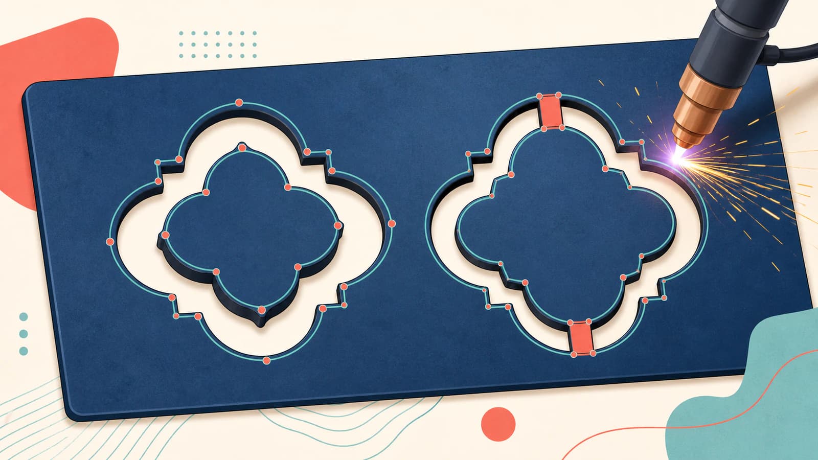
Add bridges deliberately in a vector editor before CAM, or in CAM if your documented workflow supports that edit. PerfectVector does not invent them because it cannot know whether you want an interior piece removed, retained, or cut separately.
Audit the SVG before it reaches CAM
Review the file at its final physical size. Zooming into a path is useful for editing, but it can hide a feature that becomes a hairline when the sign is scaled down.
| Check | What to look for | What to do |
|---|---|---|
| Islands and bridges | Any enclosed piece with no connection to the surrounding metal | Add a bridge, remove the island, or make it an intentional separate part |
| Intended holes | Negative spaces that should cut out, including counters and mounting holes | Confirm they remain visible and are represented by the intended closed subpaths |
| Closed contours | Gaps, self-intersections, overlapping endpoints, or accidental open strokes | Join or redraw the boundary before toolpath generation |
| Duplicate cuts | Two nearly identical outlines or both sides of a traced hairline | Delete the duplicate or fix the double-line trace |
| Small features | Narrow bridges, tight slots, sharp tips, and tiny holes | Enlarge, simplify, or test them for the actual process |
| Path density | Jagged curves built from many short segments or excessive nodes | Retrace or simplify carefully; use the DXF segment diagnosis if export makes it worse |
SVG paths can contain closed subpaths, including compound shapes with enclosed regions; the SVG 2 path specification defines how those subpaths and close-path commands work. That is a file-structure fact, not proof that your CAM will interpret every fill or winding rule the way the drawing app did. Inspect the imported geometry rather than relying on the browser preview.
There is no universal minimum bridge or hole size
Do not copy one bridge width from a forum and treat it as a plasma standard. The smallest reliable feature changes with material type and thickness, torch and consumable condition, height control, motion accuracy, amperage, speed, and air quality. Swift-Cut presents its own hole-tolerance rule as a guide and calls out several of those process variables in its hole-tolerance notes.
Use the machine, torch, and CAM vendor's recommendations as your starting point. Then cut a small coupon in the same material and thickness. A bridge that survives in thin mild steel may behave differently in thicker plate, stainless, or aluminum.
Convert the image without tracing every pixel
Once the artwork has a clear silhouette, convert it into vector paths. PerfectVector's CNC converter handles the raster-to-vector stage and provides supported SVG or DXF output. What matters is the geometry inside that file: intentional boundaries, manageable path density, and separate regions you can inspect.
Check the preview for:
- a clean outer silhouette rather than a fuzzy halo around the source;
- intentional interior holes rather than filled-in counters;
- no traced background rectangle or dust-sized fragments;
- curves that stay smooth without a node at every pixel change.
If the automatic result changes a mechanically important dimension, redraw that feature in CAD or your vector editor. An image trace follows visible edges; it is not a dimensional reconstruction of an engineered part.
Choose SVG or DXF for the receiving workflow
The right handoff format is the one your exact CAM version documents. SheetCAM's current manual lists both SVG and DXF among its import formats and then handles tools, kerf width, operations, toolpaths, and post processing inside CAM (SheetCAM TNG Manual). Other plasma workflows may prefer DXF or impose their own SVG limitations.
If both formats are supported, make a small import test before converting a library of designs. Check:
- the overall dimensions against a known measurement;
- the number and location of contours;
- whether holes remain holes;
- whether curves arrive smoothly or as many short segments;
- whether any duplicate or open geometry appears.
The container alone does not fix bad geometry. SVG versus DXF for cutting explains the compatibility and unit trade-offs, while DXF files with too many segments covers what to do when a clean curve becomes a dense chain of entities.
Finish the job in CAM, not in the converter
PerfectVector stops at the vector handoff. It does not generate G-code, select a plasma process, or choose kerf compensation, feed, current, pierce delay, lead-ins, cut order, torch height, or material settings.
Those decisions belong in your CAM and machine workflow. In SheetCAM, for example, the documented process covers tool definitions, plasma-specific tool values, operations, toolpaths, and post processing after import. Your machine and consumable documentation remains the authority for safe operating parameters.
Before cutting the finished piece:
- confirm real-world scale and material thickness;
- assign the intended inside and outside contours;
- inspect lead-ins so they do not scar the kept edge;
- review cut order, especially for small interior parts;
- simulate or preview the entire toolpath;
- run a same-material coupon before committing a valuable sheet.
The preview should answer a blunt question: after every highlighted contour is cut, which pieces are still attached?
When a direct trace is the wrong workflow
Some projects should not start with automatic vectorization.
- Dimension-critical brackets and machine parts: redraw them in CAD from verified measurements. A photograph can introduce perspective and lens distortion.
- Detailed portraits and tonal art: simplify them into a stencil or use a process meant for continuous tone, such as engraving.
- Very fine line drawings: enlarge and simplify the design, or choose a process that can reproduce the detail reliably.
- Damaged scans: repair the source or redraw key contours before tracing. Noise becomes geometry.
Vectorization is strongest when the design is fundamentally graphic. Use it to save the manual tracing work, then make the physical decisions yourself.
FAQ
Can I turn a photo into an SVG for plasma cutting? Yes, if you first stylize the photo into bold, connected light and dark regions. A direct trace of shading and texture usually creates too many small contours for a practical silhouette. For a portrait, plan where facial features connect just as you would design a stencil.
Should I send SVG or DXF to a plasma cutter? Use the format supported by the receiving CAM software and shop. SheetCAM documents both SVG and DXF import, but another workflow may prefer DXF. Verify scale, holes, curves, and contour count after import rather than assuming the two files behave identically.
Will an image converter add bridges to loose islands? Not reliably, because the converter cannot know which interior pieces you intend to keep. Add and inspect bridges deliberately in a vector editor or a documented CAM workflow before cutting.
Does PerfectVector generate plasma G-code or choose kerf settings? No. PerfectVector converts the source image into vector geometry and provides supported SVG or DXF output. CAM software generates the toolpath and post-processed machine code; you choose the plasma settings for your machine, consumables, material, and job.
How small can a plasma-cut hole, slot, or bridge be? There is no machine-independent number. Reliable size depends on the equipment, material and thickness, consumables, air, torch height, motion, current, and speed. Follow the relevant vendor guidance and test a coupon at the intended scale.
Sources
- W3C — SVG 2 Paths — Defines path data, compound subpaths, and close-path behavior used by SVG geometry.
- SheetCAM — TNG Manual — Documents SVG and DXF import, plasma-tool fields, toolpath setup, and post processing.
- Swift-Cut — Hole Tolerances — Explains that plasma-hole quality depends on equipment and process variables and presents its sizing rule as a guide.
- Xometry — Sheet Cutting Tips — Illustrates the use of bridges to retain otherwise free-floating interiors in cut sheet designs.
- PerfectVector — SVG and DXF for CNC — States the current raster-to-vector workflow and supported CNC handoff formats.
Start with artwork you are allowed to use, convert it to SVG or DXF for CNC, and run the island, bridge, contour, and scale checks before CAM. The result is a cleaner handoff and a much better reason to trust the first test cut.
More from the blog

SVG Kerf Compensation: Size Parts and Holes Correctly
Use an idealized SVG badge to understand inside and outside kerf offsets, separate cut width from path offset, and avoid applying compensation twice.

FreeCAD Image to Sketch: Build Editable Geometry
Choose the right FreeCAD image-to-sketch workflow: trace a scaled reference for exact CAD work, or convert suitable flat artwork to DXF and clean it up.