
SVG Kerf Compensation: Size Parts and Holes Correctly
Use an idealized SVG badge to understand inside and outside kerf offsets, separate cut width from path offset, and avoid applying compensation twice.
On this page
Kerf compensation moves the laser's path toward the material you intend to discard. For an outside profile, move the path outward so the retained part keeps its intended size. For a hole, move the path inward, into the hole's waste. Choose one place to apply that adjustment: the drawing, the cutting software, or the fabrication service.
Keep the full cut width separate from the path offset. In an idealized cut that removes 0.20 mm evenly around its centerline, the edge lies 0.10 mm from that line. The 0.20 mm value in this article is an assumption for the geometry example, not a recommended setting for your laser or material.
Follow the edge of the retained material
Our original badge has a nominal outside diameter of 10.00 mm and a central hole of 4.00 mm. “Nominal” means the dimensions intended for the finished part.
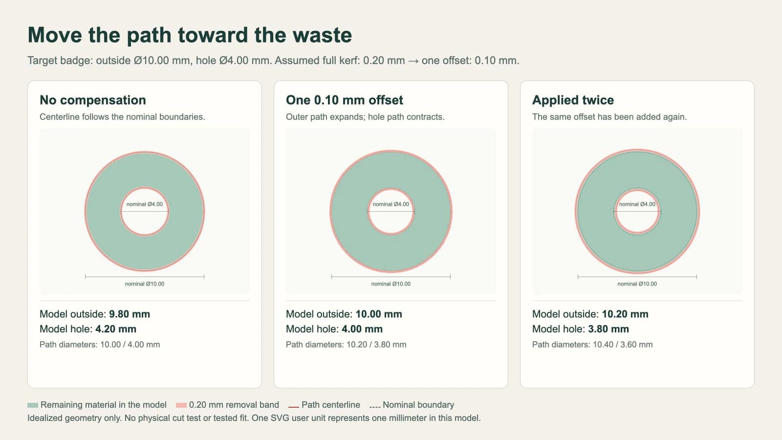
If the beam follows those nominal contours without compensation, half the kerf reaches into the material being kept at each edge. Under the stated uniform 0.20 mm assumption:
- The outside diameter becomes
10.00 − 0.20 = 9.80 mm. - The hole diameter becomes
4.00 + 0.20 = 4.20 mm.
The directions differ because the retained material is inside the outer contour but outside the hole contour. To preserve it, move both paths toward their respective waste regions.
| Feature | Nominal diameter | Centerline diameter after one offset | Model result after material removal |
|---|---|---|---|
| Outside profile | 10.00 mm | 10.20 mm | 10.00 mm |
| Hole | 4.00 mm | 3.80 mm | 4.00 mm |
Each path moves by 0.10 mm radially. Its diameter changes by 0.20 mm because a diameter spans two edges. Entering the full 0.20 mm as a radial offset would double the intended correction in this example.
The browser fixture reads the circle dimensions and calculates the remaining outside and hole diameters. It demonstrates the offset arithmetic only. It does not simulate heat, taper, material variation, or the behavior of a particular laser.
Preserve a nominal SVG master
This complete SVG stores the uncompensated badge. Its page is 14 mm square; the two circles are 10 mm and 4 mm in diameter.
<svg xmlns="http://www.w3.org/2000/svg" width="14mm" height="14mm"
     viewBox="0 0 14 14">
  <g fill="none" stroke="black" stroke-width="0.02">
    <circle cx="7" cy="7" r="5"/>
    <circle cx="7" cy="7" r="2"/>
  </g>
</svg>
The thin stroke makes the circles visible. It does not tell every importer how wide the laser cuts or assign a cutting operation. After import, verify the outside diameter is 10 mm, the hole is 4 mm, and both contours belong to the intended operation.
Use the nominal master when changing materials or sending the design to a different shop. If a workflow requires compensation baked into the geometry, make a separate copy and record the offset and its direction. Do not silently replace the dimensional master with that copy.
Check units before diagnosing kerf. A file imported at the wrong scale needs a scale correction first. The SVG versus DXF laser guide covers the format and import checks.
Read what the cutting software's field means
A setting that asks for full kerf width and one that asks for path-offset distance require different numbers. For our symmetric example, those quantities are 0.20 mm and 0.10 mm respectively. Follow the receiving program's definition instead of transferring a number based only on the word “kerf.”
LightBurn documents Kerf Offset in its Line Mode settings: a positive value moves the path outward, while a negative value moves it inward. The setting offsets the generated cut path without changing the underlying artwork. The feature requires closed shapes.
For the badge's two nested contours on the same layer, a further rule matters. LightBurn automatically reverses the offset direction for shapes inside other shapes on that layer. An outward setting for the outer profile therefore gives the nested hole the opposite treatment. Do not add a separate inward correction to that hole without checking how the complete nesting and layer setup will be interpreted.
Inspect the resulting paths in Preview. The unchanged drawing alone cannot show whether the output offset is correct. Check the outside, the opening, and the space between adjacent parts.
LightBurn's separate Offset Shapes tool creates new drawing geometry. That is a different operation from its output-time Kerf Offset. If you use Offset Shapes to prepare compensated contours, keep the original master and prevent another kerf adjustment later.
Avoid the second compensation
Suppose you have already changed the badge's SVG to an outside path diameter of 10.20 mm and a hole path diameter of 3.80 mm. Those paths contain the one 0.10 mm correction.
If the cutting stage applies another 0.10 mm in the same respective directions, the paths become 10.40 mm and 3.60 mm. After the assumed material removal, the retained part has a 10.20 mm outside and a 3.80 mm hole. The outside is too large and the opening too small relative to the nominal master.
Choose the handoff that fits the destination:
| Who owns compensation? | Geometry to hand off | Check before cutting |
|---|---|---|
| Cutting software | Nominal contours | Confirm one appropriate offset in the output settings |
| Drawing/export step | A clearly identified compensated copy | Confirm the downstream stage will not offset it again |
| Fabrication service | The geometry that service requests | Follow its preparation rules and tolerance guidance |
For example, SendCutSend asks customers not to compensate their designs for kerf. It handles that adjustment and asks for the desired part dimensions. That is a service-specific instruction, not a rule that every laser workflow behaves the same way.
Enlarging the whole badge is also the wrong correction for this example: it increases both the outer diameter and the hole. The required compensated paths increase one diameter and decrease the other.
Calibrate the actual job separately
The example's arithmetic cannot supply your machine's value. LightBurn's kerf test guide explains that kerf depends on material, thickness, and cutting settings. Its test starts with Kerf Offset at zero and calculates a value to use as the offset setting. If a test already returns an offset, do not halve that result again as though it were full kerf width.
Use the actual material and intended cutting setup for the test, then verify a representative part and opening. Record what the result means: full removed width, path offset, or a fit adjustment. A tab that must fit a particular material thickness also needs correct design dimensions; kerf is not a substitute for those dimensions.
Before running the final job, inspect closed contours, duplicate paths, units, inside/outside classification, and the applied offset. The image-to-SVG laser workflow covers the broader path and operation checks. For a plasma workflow, use its separate preparation guide and the receiving CAM system's rules rather than reusing laser settings.
Prepare the artwork before offsetting it
When the source is a PNG or JPG, PerfectVector's image-to-vector converter can recover candidate artwork boundaries. Inspect those contours for gaps, duplicate edges, and unwanted islands, then set nominal dimensions and let the chosen cutting stage handle compensation. A raster trace does not establish engineering dimensions or calibrate a laser.
Keep an existing CAD or vector master when one is available. For a dimension-critical circle, slot, or tab, construct the feature numerically instead of relying on pixels to define its size. The image vectorization guide explains where tracing fits in that process.
FAQ
Should an inside hole get the same offset direction as the outside profile? No. To preserve the retained material under a symmetric kerf model, move the outside path outward and the hole path inward. Software may apply those opposite directions automatically when it recognizes nested contours.
Do I enter the full kerf width or half of it? Read the setting's definition. For a symmetric cut, a path-offset distance is half the full removed width. A field that requests full kerf width takes the full value. A calibration result already expressed as an offset should not be halved again.
Can I compensate in the SVG and again in LightBurn? Applying the same correction twice overcompensates the geometry. Preserve nominal artwork and choose one compensation stage, or clearly identify a precompensated copy and disable the repeated adjustment downstream.
Sources
- LightBurn — Line Mode — Documents Kerf Offset direction and its effect on the generated path.
- LightBurn — Kerf and offset testing — Explains nested-shape handling, Preview, and the calibration workflow.
- LightBurn — Offset Shapes — Distinguishes creating offset drawing geometry from output-time compensation.
- SendCutSend — Kerf compensation in submitted designs — States that the service handles kerf and requests the desired dimensions.
If your cutting project starts with raster artwork, prepare an SVG candidate with PerfectVector, inspect its boundaries, and establish nominal dimensions before applying one verified compensation step in the cutting workflow.
More from the blog

Convert an Image to SVG With Clean CNC Cut Paths
A CNC follows vector paths, not pixels, so your design has to become a clean SVG or DXF first. Here's how to convert an image into CAM-ready, closed-path vectors.

Make Clean SVG Files for Glowforge From Any Image
Make Glowforge-ready SVG files from your own images: what the app accepts, how strokes become cuts and fills become engraves, and a clean no-Illustrator path.