
QCAD Trace Bitmap: Contours or Measured CAD Geometry?
Use QCAD Professional's Trace Bitmap for image contours, compare manual CAD tracing, and check line meaning, scale, and cleanup before handing off a DXF.
On this page
QCAD's Trace Bitmap tool turns an inserted image into polylines. It belongs to the QCAD Professional add-on and is available through Draw > Trace Bitmap, according to the current command reference.
Use it when you want the visible contours of artwork. If a thick mark represents one centerline, or a radius must match a measured part, decide that geometry yourself and draw it with CAD tools. A contour trace cannot make that design decision for you.
The useful first question is what the finished DXF should contain: an outline of the ink, a single line through it, or a measured feature. That choice determines whether automatic tracing is a useful starting point.
A thick stroke can mean two different things
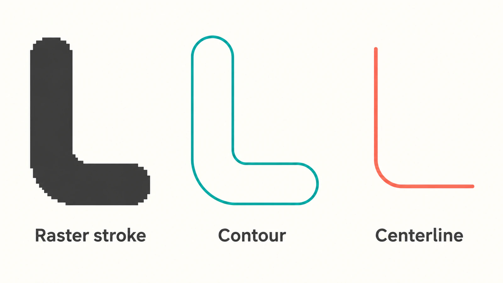
Imagine a broad L-shaped brush mark with a rounded bend. For a decorative cutout, you might want the perimeter of the entire mark. For a path that a tool follows once, you might need one line through its middle. Both drawings can resemble the same source at a distance, but they describe different operations.
A boundary trace follows the ink's perimeter, including its two sides and end caps. A deliberately drawn centerline uses a single path through the mark. The centerline's position and bend radius still need a reason: measured endpoints, specified dimensions, or a design choice. Do not assume either edge of the ink is the intended location.
| Required result | Useful starting method | What to verify |
|---|---|---|
| Decorative silhouette or artwork perimeter | Automatic contour tracing | The outline includes the intended details and excludes background noise |
| A single path along a thick mark | Draw the intended line or arc deliberately | Endpoints, bend location, and whether one path serves the operation |
| A part with specified lengths, hole locations, or radii | Reconstruct from measurements in CAD | Dimensions and relationships, independent of the raster edge |
QCAD's official tracing tutorial demonstrates both ordinary CAD tools and automatic tracing. It also cautions that an automatic trace is not a precise way to recover a CAD drawing from an arbitrary photo.
Insert the image without confusing it with vectors
Choose Draw > Insert Bitmap, select the source image, and set its width or height in drawing units before placing it. QCAD's Insert Bitmap reference documents those placement controls and PNG transparency support.
Keep the raster on a reference layer and place your new geometry on a separate layer. A contrasting layer color makes it easier to tell your work from the source. When inspecting a trace, hide the image layer so the original pixels do not conceal gaps or fragments.
Save the source image beside the drawing. QCAD references an inserted bitmap from the drawing file; saving the drawing does not embed the image itself. Keeping both files together helps the image remain available when you reopen the drawing. This behavior is documented in the bitmap reference.
Setting the image width is useful placement, but it does not prove that a scanned feature has the right dimensions. If the scan needs calibration, use a known measurement and check another feature afterward. The floor-plan tracing and scale guide explains why a single matching length cannot establish that an entire scan is undistorted.
Run Trace Bitmap on a small representative area
Start with a copy containing one meaningful detail: the bent stroke, a notch, or a small opening that must survive. A tightly chosen sample is easier to inspect than a whole scanned sheet.
- Insert and select the image.
- Make the layer for the new geometry current.
- Open Draw > Trace Bitmap.
- Choose the preprocessing settings, then use Update to inspect the preview.
- Confirm with OK. QCAD adds the resulting polylines to the current layer.
The command sequence and output are documented in the Trace Bitmap reference. If that command is missing, first check the edition and version you installed. A reference page for a Professional command does not establish that it is included in Community Edition.
Adjust the preview for the contour you want
For a silhouette, try monochrome preprocessing. In QCAD's tutorial example, a brightness-based threshold separates a hammer from a white background while suppressing unwanted interior details. A transparent source calls for attention to alpha instead. Judge the preview by the shape you need to retain, rather than copying somebody else's threshold value.
If a notch vanishes, compare the setting with the source before continuing. If the background becomes a collection of tiny contours, inspect whether its texture is being treated as artwork. Change one control, update the preview, and compare that same feature again.
For color tracing, the command also offers a palette-size setting. Reducing the number of colors can discard details or noise; retaining more can preserve either. This tradeoff is described in the command reference. Pick the smallest palette that keeps the regions your job actually needs, then inspect the output with the bitmap hidden.
Check the result before saving a delivery DXF
A trace is ready to hand off when its geometry matches the intended task. For the bent-stroke example, inspect the two sides, both end caps, and the inner bend. Confirm whether the operation needs that closed perimeter or the single path shown in the illustration.
Use a copy of the drawing for cleanup:
- Remove confirmed background contours and specks. Preserve small details that belong to the design.
- Inspect apparently straight or circular portions. Redraw them from the intended geometry when the job requires a line or a true arc.
- Check whether separate pieces should meet. A visible join at normal zoom is not enough to accept a gap-sensitive contour.
- Measure a known feature and verify a second feature away from it.
- Reopen the delivery file in the receiving CAD or CAM application and inspect the actual geometry it uses.
If the trace contains too many small segments, use the DXF entity and vertex diagnosis before simplifying. Joining pieces into one selectable polyline does not necessarily remove its excess vertices. Aggressive cleanup can also alter the inner bend you were trying to preserve.
For machining, continue with the image-to-vector CNC handoff checks, including the destination's contour selection and toolpath preview. A saved DXF is an exchange file, not confirmation that a machine will follow the intended path.
When an external image-to-DXF step helps
If you have a raster emblem and want an external vector candidate before editing in QCAD, convert the image to DXF with PerfectVector. Use a clear source, inspect the vector preview for unwanted regions and lost details, then download and open the DXF in the destination. Verify the contours, entity structure, and known dimensions there. This can supply artwork geometry; it does not infer the centerline or dimensional intent of a technical drawing.
If QCAD Professional's native trace already gives you a useful outline, continue with its cleanup tools. If the drawing needs measured lines, arcs, and hole locations, construct those directly. Choose between the workflows using your own sample, rather than assuming a different converter will solve a geometry decision.
For a new vector user, the image vectorization primer explains why recovering visible artwork and rebuilding the design's meaning are separate tasks.
FAQ
Is Trace Bitmap included in free QCAD Community Edition? The current command reference labels Trace Bitmap as a QCAD Professional add-on. Manual drawing over an inserted image is a separate workflow. Check your installed edition before looking for the automatic command.
Why does a thick line produce two traced sides? A contour follows the boundary of the ink. A broad stroke has two sides, so its perimeter differs from a single path down its middle. Draw the intended centerline when that is what the next operation requires.
Does saving a DXF keep the inserted image inside the file? QCAD's bitmap insertion documentation says the drawing stores a reference to the image. Keep the image file with the drawing if you need the raster underlay when reopening it.
Can a bitmap trace recover exact CAD dimensions? Do not treat the trace as dimensional authority. Use known measurements, check more than one feature, and construct critical lines, arcs, and hole positions from the required geometry.
Sources
- QCAD — Trace Bitmap — Professional availability, preprocessing controls, and polyline output.
- QCAD — Tutorial 2.6: Tracing Images — Manual and automatic tracing workflow with stated precision limits.
- QCAD — Insert Bitmap — Image placement, dimensions, transparency, and external file references.
Decide whether the next job needs a contour, a centerline, or measured CAD geometry. For a raster artwork contour, make a DXF candidate, hide the source image, and inspect the bend, endpoints, and known size before handing it off.
More from the blog

AutoCAD Raster to Vector: Choose the Right Workflow
Separate an attached image from editable CAD entities. Choose Raster Design, manual reconstruction, or an artwork DXF, then verify what AutoCAD contains.

SVG in WPF: Choose a Renderer or a XAML Drawing
Use SVG artwork in WPF with a renderer, a native DrawingImage, or a PNG export. Follow an original icon example and check bounds, colors, and dependencies.