
AutoCAD Raster to Vector: Choose the Right Workflow
Separate an attached image from editable CAD entities. Choose Raster Design, manual reconstruction, or an artwork DXF, then verify what AutoCAD contains.
On this page
- One scanned plaque, three different jobs
- Check whether you have an image reference or geometry
- Check Raster Design availability before following a tutorial
- Use interactive tools for the entities you intend to edit
- A clean entity still needs the right dimensions
- Prepare decorative artwork as a separate DXF candidate
- Verify the handoff by object and operation
- FAQ
- Sources
To convert an image to vectors for AutoCAD, choose the objects the drawing needs. IMAGEATTACH links an image as a reference; it does not turn the marks inside that image into separate drawing geometry. Autodesk's command reference describes that attachment behavior.
For editable CAD geometry, use deliberate drawing tools or Raster Design's interactive vectorization tools. For decorative artwork, an external image-to-DXF conversion can provide outlines to inspect in AutoCAD. None of these choices makes an arbitrary scan a reliable source of engineering dimensions.
Start by deciding whether you need to see the image, edit a geometric feature, or reuse the artwork's outline. That decision saves you from accepting a drawing that looks complete but contains the wrong objects.
One scanned plaque, three different jobs
Consider an arch-topped plaque with a circular mounting hole and a leaf decoration. You receive a scan showing all three.
If the scan is a visual reference for arranging a presentation drawing, attaching it may be enough. If you must change the hole diameter or the top arc's radius, you need geometry representing those features. If the job is to engrave the leaf, you may only need its decorative outline.
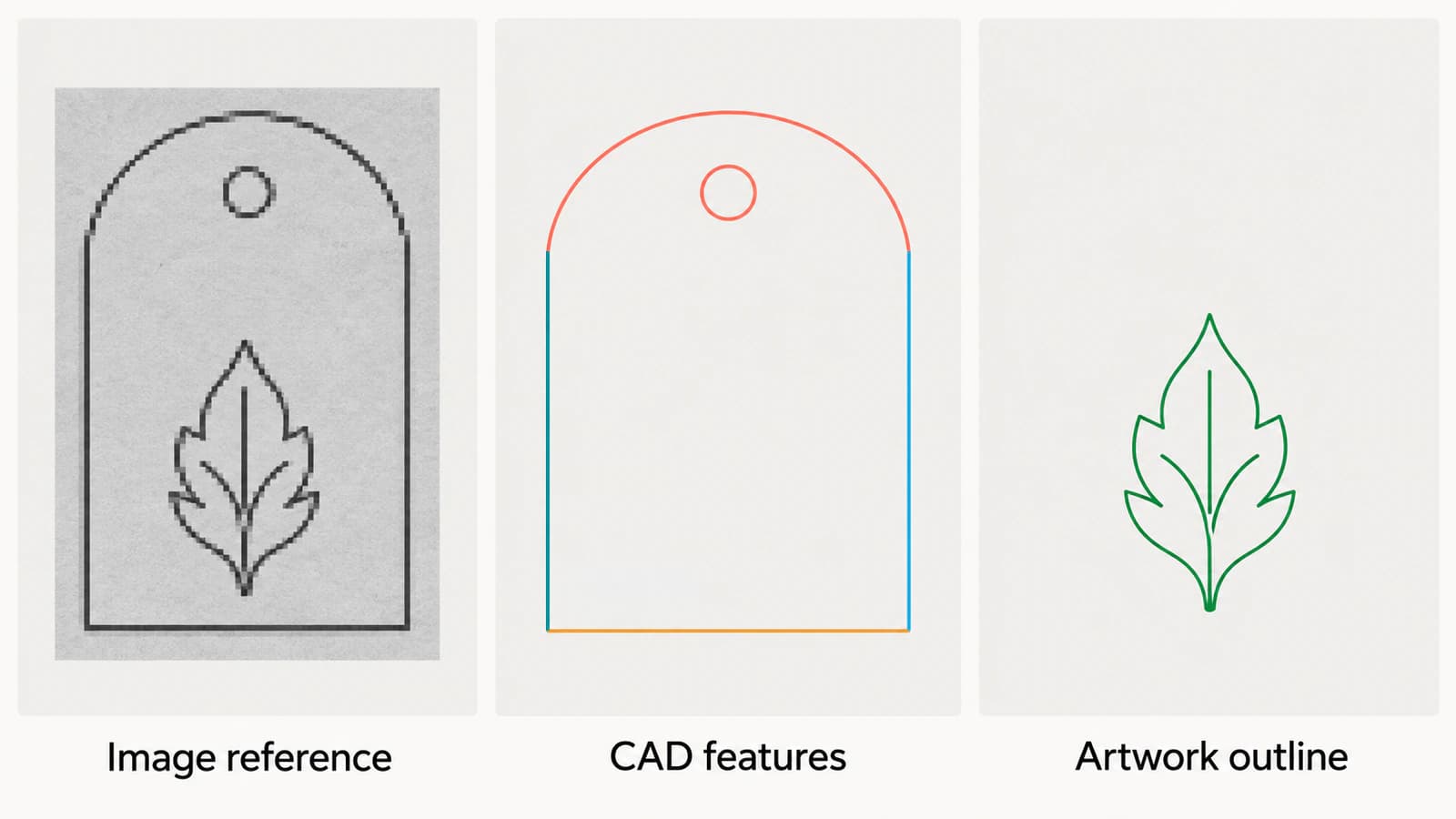
| What the job needs | Starting workflow | Acceptance check |
|---|---|---|
| The scan visible beside other drawing content | Attach the image | Reference appears at the intended position and remains available |
| Editable straight edges, top arc, and mounting hole | Draw from dimensions or use interactive Raster Design tools | Required features have the intended entity type and geometry |
| A leaf motif for an artwork handoff | Trace the artwork and open a DXF candidate | Intended contours survive and the receiver can use them |
These workflows can coexist in one drawing. Keep the scan, reconstructed features, and artwork on separate layers so each has a clear purpose.
Check whether you have an image reference or geometry
Select the object and inspect what AutoCAD reports. A frame around an entire image does not demonstrate that the hole inside it is a circle entity. Try selecting the required feature itself, then temporarily hide the image layer to see what remains.
For the plaque example, hiding the scan should leave the reconstructed boundary and hole visible if those objects have been created. If the drawing becomes empty, the image was providing the appearance you were relying on.
When you use IMAGEATTACH, keep track of the referenced image file. Autodesk documents that the drawing links to that file and can display its changes when reopened or reloaded. An attachment is useful, but handing someone only the drawing may leave them without the referenced source.
The DXF entity guide explains the same inspection principle at file level: an exchange format's extension cannot tell you which useful geometry it contains.
Check Raster Design availability before following a tutorial
Autodesk's support guidance says Raster Design is included with AutoCAD specialized toolsets but must be installed separately. Seeing AutoCAD on your computer does not establish that Raster Design's commands are installed.
Also check the host application and platform:
- Autodesk's AutoCAD LT support note says Raster Design requires full AutoCAD or an AutoCAD toolset.
- Autodesk's specialized-toolset system requirements identify the toolsets as Windows only. Do not expect the same Raster Design commands in native AutoCAD for Mac.
Use the help that matches your installed release. If Raster Design is unavailable, you can still decide which features to reconstruct manually or which decorative region to prepare externally. You do not need to convert an entire scan just to obtain one leaf motif.
Use interactive tools for the entities you intend to edit
Autodesk's Vectorizing Raster Geometry guide documents separate tools for lines, polylines, rectangles, circles, and arcs. It describes a one-pick method for bitonal raster lines and a multi-pick method that gives you more control over the selected geometry.
For the plaque, choose the feature before choosing the tool. A mounting hole calls for a circle; a straight side calls for a line; the rounded top calls for an arc. Treat the leaf separately instead of attempting to explain every part of the scan with one entity type.
A useful sample workflow is:
- Keep a copy of the source and isolate one straight side, the top arc, and the hole.
- Choose the vectorization tool appropriate to each feature.
- Use the documented one-pick or multi-pick selection method for the source.
- Review the resulting geometry before moving to the next feature.
- Hide the image and inspect the new objects independently.
The same Autodesk guide describes checking line angle and length, reversing endpoints, and trimming or extending after vectorization. It also documents options affecting raster removal and conformance to drafting settings. Check those settings before working through a whole sheet so the tool's behavior matches your plan.
A clean entity still needs the right dimensions
A circle entity is easier to reason about than a ring made from arbitrary fragments, but it can still have the wrong diameter or position. Choose those values from the design requirements, a trustworthy dimensioned source, or measurements of the part.
For the plaque, check the hole diameter, its center relative to the sides, and the overall width. Matching the width alone does not establish that the scanned arc or hole is correct. A skewed or stretched source needs more than one matching measurement.
For plans and scans, use the scale and distortion checks before relying on traced geometry. Reconstruct critical features from the intended dimensions when the raster cannot support them.
Prepare decorative artwork as a separate DXF candidate
If the job only needs the leaf decoration, crop a copy of the source around that motif. Exclude the plaque border, mounting hole, dimension marks, and scan debris unless they belong to the artwork you intend to reuse.
Convert the artwork image to DXF with PerfectVector, inspect the vector preview for missing leaf tips and unwanted background regions, then download and open the DXF in AutoCAD. Keep the imported artwork on its own layer. Check its contours and size with the original image hidden before placing it in the plaque drawing.
This supplies an artwork candidate. It does not establish the hole diameter, reconstruct engineering constraints, or promise that every curved contour arrives as a native arc. Inspect the actual imported entities and decide whether they serve the next operation.
If a native Raster Design workflow already gives you the objects you need, continue there. If a few measured features determine the whole design, drawing them directly can avoid tracing irrelevant scan detail. For the wider distinction between recovering visible artwork and rebuilding design meaning, see the image vectorization primer.
Verify the handoff by object and operation
Before delivering the drawing or DXF, check the three parts of the plaque separately:
- Reference: the image is visible when required, and its source file remains available.
- CAD features: the side, arc, and hole can be selected as the intended objects, and their geometry matches the requirements.
- Artwork: the leaf contains the intended contours without the surrounding page or unwanted marks.
Then reopen the delivery file in the application that will use it. Repeat a small edit, such as changing a copied hole's diameter, or select the artwork contour for the intended downstream operation. Keep that test in a copy.
For CNC work, continue with the vector-to-CAM handoff checks. A drawing that displays correctly still needs a destination-specific toolpath preview and dimensional checks.
FAQ
Does attaching a JPG in AutoCAD convert it to lines? No. IMAGEATTACH creates a reference to the image file. Create or import separate geometry if you need to edit the marks inside it as drawing objects.
Can AutoCAD LT run Raster Design? Autodesk's support guidance requires full AutoCAD or an AutoCAD toolset for Raster Design. Check your installed product before following a Raster Design tutorial.
Will an image-to-DXF converter create native arcs and circles? Do not assume the entity type from the extension or appearance. Inspect the imported objects and reconstruct features whose type and dimensions are required by the job.
Can I use a traced scan as an exact engineering drawing? Use verified dimensions and design requirements for critical geometry. A trace can help recover visible features, but it does not establish their intended dimensions, relationships, or tolerances.
Sources
- Autodesk — IMAGEATTACH — Image references and reload behavior.
- Autodesk — Raster Design inclusion and installation — Toolset availability and separate installation.
- Autodesk — Raster Design and AutoCAD LT — Supported host application requirement.
- Autodesk — AutoCAD specialized-toolset system requirements — Windows-only toolset platform.
- Autodesk — Vectorizing Raster Geometry — Geometry-specific interactive tools and result editing.
Choose what must remain when the image is hidden. Build measured CAD features from the required geometry; for a decorative motif, prepare an artwork DXF and verify its contours, size, and imported objects before placing it in the drawing.
More from the blog

QCAD Trace Bitmap: Contours or Measured CAD Geometry?
Use QCAD Professional's Trace Bitmap for image contours, compare manual CAD tracing, and check line meaning, scale, and cleanup before handing off a DXF.

SVG in WPF: Choose a Renderer or a XAML Drawing
Use SVG artwork in WPF with a renderer, a native DrawingImage, or a PNG export. Follow an original icon example and check bounds, colors, and dependencies.