Is DXF a Vector File? How to Trace or Export It
DXF is a CAD vector format, but the extension alone does not guarantee usable geometry. Learn when to export, when to trace, and what to verify after import.
On this page
- What makes DXF a vector format
- DXF versus SVG, in practical terms
- Export, trace, or keep raster?
- Export when geometry already exists
- Trace when the source is flat raster artwork
- Keep raster when continuous tone is the point
- How to turn an image into a useful DXF
- 1. Define what the receiver needs
- 2. Prepare the best source
- 3. Trace the required geometry
- 4. Set and verify units
- 5. Inspect the imported entities
- 6. Preflight the manufacturing geometry
- How to tell whether a DXF contains useful vector geometry
- Common DXF problems
- The file opens at the wrong size
- Curves look faceted
- Filled artwork becomes outlines
- A cutter follows every edge twice
- DXF handoff checklist
- FAQ
- Sources
Yes, DXF is generally classified as a vector file. It stores drawing geometry as entities such as lines, arcs, polylines, circles, and splines rather than flattening the drawing into one pixel grid. That makes DXF useful for exchanging work between CAD, CAM, cutting, and fabrication applications.
The useful answer needs one qualification: .dxf describes a drawing-data format, not a guarantee that every item inside is a clean 2D contour. A DXF can hold layers, blocks, dimensions, 3D entities, non-graphical objects, and even image references. You still have to inspect what the receiving application imports.
Short answer
- Already have CAD or vector geometry? Export it to the DXF version and units the receiver requests.
- Starting from a flat PNG or JPG? Trace suitable artwork into paths, then write those paths as DXF entities.
- Starting from a photo or tonal scan? Keep it raster unless the goal is a deliberately simplified contour drawing.
- Before manufacturing: verify a known dimension, units, closed contours, doubled lines, layers, and the actual toolpath.
What makes DXF a vector format
Adobe's DXF overview places it in the vector family because individual components can be edited and scaled as geometry. Autodesk's own DXF format documentation is more precise: DXF is a tagged-data representation of drawing information, with group codes that describe each data element.
In other words, DXF is not a picture of a drawing. It is a structured description of the drawing.
That structure can include:
- geometric entities such as lines, arcs, circles, polylines, and splines;
- layers, linetypes, and styles;
- block definitions and inserted block references;
- dimensions, text, hatches, and other CAD entities;
- drawing metadata and non-graphical objects;
- 2D or 3D coordinates, depending on the source drawing.
Autodesk's general DXF structure reference separates header, tables, blocks, entities, objects, and an optional thumbnail section. The graphical work mainly lives in the BLOCKS and ENTITIES sections. The extension alone does not tell you whether those entities suit your destination.
DXF versus SVG, in practical terms
Both formats can carry vector geometry, but they grew up in different workflows.
| Question | DXF | SVG |
|---|---|---|
| Primary role | Exchange CAD drawing data | Display and edit scalable graphics |
| Typical geometry | Lines, arcs, polylines, splines, blocks | Paths, shapes, strokes, fills |
| Appearance | CAD properties and layer organization | Rich fill, stroke, gradient, and web styling |
| Units | May declare drawing units or arrive unitless | May use physical dimensions, viewBox, or CSS-like units |
| Common destination | CAD, CAM, CNC, plasma, laser, fabrication | Browsers, design apps, web, desktop cutters |
| Best choice | When the receiver requests CAD geometry | When the receiver values graphic appearance or SVG paths |
Use the format requested by the receiving software, vendor, or machine workflow. Converting to DXF because it “sounds more precise” does not improve poor geometry. It only changes the container.
The laser-specific tradeoffs are covered separately in SVG versus DXF for laser cutting. This guide stays with the broader vector, trace, and export decision.
Export, trace, or keep raster?
Export when geometry already exists
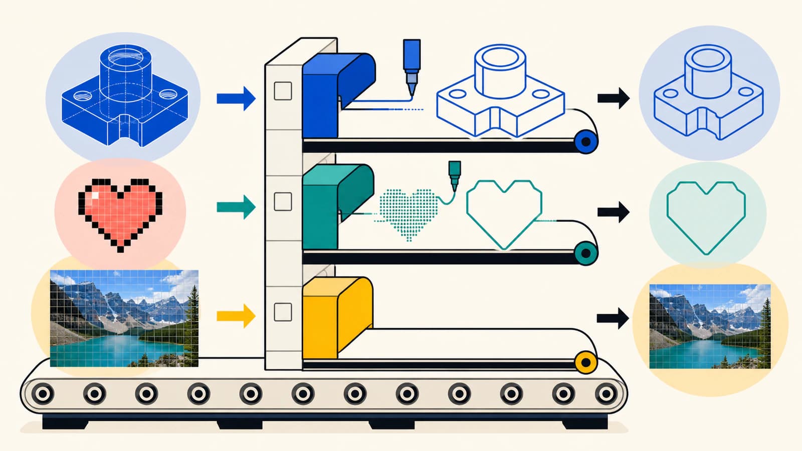
If the drawing is already made from CAD entities or vector paths, do not rasterize it and trace it again. Export or save a copy as DXF from the source application. Re-tracing introduces approximation, extra nodes, and possible scale drift for no benefit.
This applies to measured CAD sketches, vector logos, technical diagrams, and cut contours. Convert live text to outlines only when the receiver cannot access the font and editable text is not required. Ask which DXF version, units, and entity types the destination accepts.
Trace when the source is flat raster artwork
A PNG, JPG, BMP, or scanned drawing contains pixels. Renaming it .dxf or placing it as an image reference does not create line, arc, or polyline entities. A tracer must infer boundaries and rebuild them as geometry.
For AutoCAD, compare the AutoCAD attachment, Raster Design, and artwork DXF choices to decide whether the drawing needs a visible reference, deliberately created CAD entities, or decorative outlines.
This can work well for:
- a bold black-and-white logo;
- a simple sign silhouette;
- clean line art;
- a limited-color illustration that needs closed contours;
- a scanned template used as a redraw underlay, followed by dimensional calibration.
Expect more cleanup for blur, shadows, gradients, textured paint, compression blocks, or intersecting thin strokes.
Keep raster when continuous tone is the point
A photograph, shaded rendering, or watercolor does not naturally reduce to a small set of manufacturing contours. A trace can posterize it into many regions, but that is a new interpretation rather than a faithful vector equivalent.
If the destination uses the pixels for engraving, printing, or reference, keep the raster and package it according to that workflow. If you only need one outer boundary, trace the silhouette rather than every tone.
How to turn an image into a useful DXF
1. Define what the receiver needs
Ask whether the job requires centerlines, closed outlines, color-separated contours, layers, 2D geometry, or something else. A plasma cutter that needs closed profiles has a different definition of “good DXF” from a CAD user importing a reference sketch. For that CAD case, the SolidWorks image-to-sketch route separates native reconstruction, Picture to Sketch, AutoTrace, and a reviewed DXF handoff.
Also confirm the expected unit and DXF version. Do this before conversion so the verification has a target.
2. Prepare the best source
Use the original artwork, not a screenshot of it. Crop unrelated content, remove accidental background pixels, and increase edge separation only enough to expose intended boundaries. Preserve one untouched copy.
For measured scans, include a trusted reference dimension or calibration object. A trace can preserve proportions from the image, but it does not know the physical scale on its own.
3. Trace the required geometry
Use the image-to-DXF converter to reconstruct suitable shapes. Inspect the vector preview before download. Look for:
- one contour where one cut is intended;
- closed profiles for filled or cut-out regions;
- preserved holes and counters;
- smooth curves with a sensible number of nodes;
- no background rectangle or isolated specks;
- no doubled edges caused by tracing both sides of a thick stroke.
PerfectVector can provide a clean 2D vector starting point and a DXF output for suitable artwork. It does not create parametric constraints, manufacturing tolerances, semantic CAD features, or verified engineering dimensions.
4. Set and verify units
DXF can carry unit metadata, but a drawing may also be unitless. Autodesk's INSUNITS documentation includes an explicit unspecified value alongside inches, millimeters, centimeters, meters, and other units.
Open the DXF in the receiving CAD or CAM application, choose the intended import unit if prompted, and measure a known feature. Do not rely on a familiar-looking preview. An inch-to-millimeter mismatch changes scale by 25.4.
5. Inspect the imported entities
Zoom into arcs and curves. Some export routes preserve splines or arcs; others approximate them as polylines. Neither is automatically wrong, but a coarse polyline can produce visible facets, while an excessively dense one creates unnecessary machine motion and editing cost.
Check whether blocks, hatches, text, and layer names arrived in a useful form. For a simple cutting job, plain closed contours are often more portable than elaborate CAD styling.
6. Preflight the manufacturing geometry
Before a cutter, router, plasma table, or laser receives the file:
- remove duplicate and overlapping lines;
- join gaps that should form closed contours;
- identify inner versus outer profiles;
- remove construction geometry not meant for the machine;
- confirm that no contour crosses itself;
- apply operation, tool, speed, and order settings in the actual CAM or machine software;
- simulate or preview the toolpath;
- test a representative feature on scrap when practical.
DXF carries geometry. It does not decide how that geometry should be manufactured.
How to tell whether a DXF contains useful vector geometry
You do not need to read the entire file format. Use these checks:
- Open the file in a CAD or vector application that supports DXF.
- Select an intended line or contour. It should behave as geometry, not one flat image.
- Inspect the entity or object list for lines, arcs, polylines, splines, circles, or blocks.
- Measure a known dimension.
- Hide layers one at a time and confirm their purpose.
- Run the destination's geometry or toolpath preview.
If the only visible item is an image reference, the DXF may be acting as a container or underlay rather than providing the paths you expected. Return to the original raster and trace the required shapes.
Common DXF problems
The file opens at the wrong size
The drawing may be unitless, the import unit may differ from the export unit, or the source was never calibrated. Set the intended unit and scale the entire drawing from one known dimension, then verify another dimension elsewhere.
Curves look faceted
The export or conversion may have replaced curves with sparse line segments. Re-export with supported arc, spline, or finer polyline handling, then inspect the receiving application. Do not add thousands of points blindly; use the coarsest representation that stays within the job's visual or dimensional tolerance.
Filled artwork becomes outlines
DXF workflows commonly care about entities and contours rather than rich graphic fills. Decide whether the destination needs boundaries, hatches, or separate closed regions. If appearance matters more than CAD exchange, SVG or PDF may be a better companion file.
A cutter follows every edge twice
A thick raster stroke may have been traced as a narrow closed shape, so both sides become toolpaths. If the job needs one centerline, use a centerline workflow or redraw it. If it needs a filled outline, keep the closed shape and ensure the machine operation matches.
DXF handoff checklist
- The receiver confirmed DXF, version, unit, and acceptable entity types.
- Existing vector geometry was exported, not rasterized and re-traced.
- Raster artwork was traced only where useful contours exist.
- One known dimension and one cross-check dimension are correct.
- Curves are smooth enough without unnecessary segmentation.
- Required contours are closed and non-self-intersecting.
- Doubled lines, stray entities, and construction geometry are removed.
- Layers and blocks import in a usable form.
- The final CAD/CAM or machine preview shows the intended operations.
- A raster or PDF proof accompanies the DXF when appearance matters.
FAQ
Is DXF always a vector file? DXF is classified as a CAD vector exchange format, but a particular file can also contain non-graphical data or image references. Inspect the entities to confirm that the paths or contours you need are present.
Can a PNG be converted to DXF? Yes, when a tracer rebuilds suitable pixel boundaries as vector geometry. Renaming the extension or embedding the PNG does not convert it. Flat, high-contrast artwork traces better than photographs.
Is DXF better than SVG? DXF is usually better when a CAD, CAM, shop, or machine workflow requests drawing entities and units. SVG is usually better for web and design workflows that need rich appearance.
Does DXF preserve real-world size? It can carry drawing-unit metadata, but DXF files may also be unitless and importers can apply different defaults. Measure a known feature after import before relying on the file for manufacturing.
Can DXF contain 3D data? Yes. DXF supports both 2D and 3D drawing entities. A raster-to-DXF trace normally creates 2D geometry; it does not infer a 3D model, thickness, or parametric CAD features.
Sources
- Adobe — Learn About DXF Files — Accessible overview of DXF as a vector drawing-exchange format.
- Autodesk — About the DXF Format — Defines DXF as tagged drawing data and explains group codes.
- Autodesk — General DXF File Structure — Documents header, tables, blocks, entities, objects, and optional thumbnail sections.
- Autodesk — INSUNITS — Lists drawing-unit values, including unspecified, inches, and metric units.
Have flat artwork that needs real 2D CAD contours? Convert the source image to DXF geometry, then verify its units, dimensions, entities, and final toolpath in the receiving application.
More from the blog

Convert an Image to SVG With Clean CNC Cut Paths
A CNC follows vector paths, not pixels, so your design has to become a clean SVG or DXF first. Here's how to convert an image into CAM-ready, closed-path vectors.

SVG Kerf Compensation: Size Parts and Holes Correctly
Use an idealized SVG badge to understand inside and outside kerf offsets, separate cut width from path offset, and avoid applying compensation twice.