VCarve Trace Bitmap: Turn an Image Into CNC Vectors
Use VCarve Trace Bitmap to fit vectors to a PNG or JPG, tune threshold, color, corners, and noise, then inspect the paths before making toolpaths.
On this page
VCarve's Trace Bitmap tool turns visible regions in an imported PNG, JPG, or other supported bitmap into vector boundaries. Import the image, select it in the 2D view, open Trace Bitmap (also described in the current help as fitting vectors to a bitmap), choose black-and-white or color tracing, preview the contours, and apply the result.
If the source is a legacy .bmp or .dib that you want to convert before the VCarve import, the BMP to SVG converter handles that format-specific preparation and gives you a second set of paths to inspect.
That gives you vectors, not a finished CNC job. Before creating a profile, pocket, or V-carve toolpath, inspect the trace for doubled outlines, open contours, stray fragments, excessive nodes, and the wrong physical size. A contour that looks fine over the original image can still produce a poor or impossible toolpath.
The reliable VCarve trace workflow
- Import and select the cleanest bitmap you have.
- Trace the whole image or drag a selection around the part you need.
- Choose black-and-white or color mode for the artwork, not by habit.
- Tune Threshold or color selection, then balance Corner Fit and Noise Filter.
- Preview, apply, and hide or fade the bitmap so the new vectors are visible.
- Validate contours, check scale, assign toolpaths, and preview the machining result.
How to trace a bitmap in VCarve
The current Vectric Trace Bitmap documentation describes this sequence:
- Create or open the VCarve job at the correct material size.
- Use Import Bitmap and choose the source image.
- Select the bitmap in the 2D view.
- Open Trace Bitmap under the vector-creation tools.
- If you need only one area, drag a rectangle over that part of the selected bitmap.
- Choose Black and White or Color, adjust the controls, and click Preview.
- When the red preview boundaries follow the shapes you intend to machine, click Apply.
Move the source bitmap to another layer, fade it, or hide it after applying the trace. The original pixels are useful for comparison, but they can also conceal duplicate contours and tiny artifacts.
Black-and-white or color trace?
Use black-and-white mode for silhouettes, one-color logos, and other sources where brightness cleanly separates foreground from background. Its Threshold control changes which gray values fall into the traced region. Raising the value may recover light marks, but it can also pull antialiasing, shadows, and background noise into the vectors.
Use color mode when separate flat color regions correspond to different parts of the design. Vectric documents that the imported color image is reduced to a 16-color palette, after which you can choose how many colors remain visible, link similar colors, or select colors directly in the 2D view. This is palette reduction, not recovery of the original design layers. Small variations may merge, while softened edges may still create extra regions.
| Source | Better starting mode | Watch for |
|---|---|---|
| Solid black silhouette on white | Black and White | A threshold that closes small gaps or fills intended holes |
| Scanned one-color drawing | Black and White | Paper shadow, dust, and doubled outlines around thick strokes |
| Flat two- or three-color badge | Color | Similar colors merging or antialiased edge colors becoming fragments |
| Photograph or shaded rendering | Usually neither for profile cutting | Tonal detail becoming many arbitrary closed regions |
A photograph can be useful for a separate engraving or relief workflow, but tracing it into flat boundaries does not preserve continuous tone or create 3D depth.
What Corner Fit and Noise Filter actually trade
Corner Fit changes how tightly the fitted vectors follow corners in the source. A tighter fit can preserve sharp logo geometry, but it can also follow pixel stair-steps and compression damage. A looser fit may clean a rough edge while rounding a corner that matters. Compare the preview at important corners rather than treating either end of the control as universally better.
Noise Filter sets the minimum pixel-region size that the vectorizer keeps. Raise it to drop dust and isolated specks. Stop when punctuation, narrow islands, small counters, or other intentional details begin to disappear.
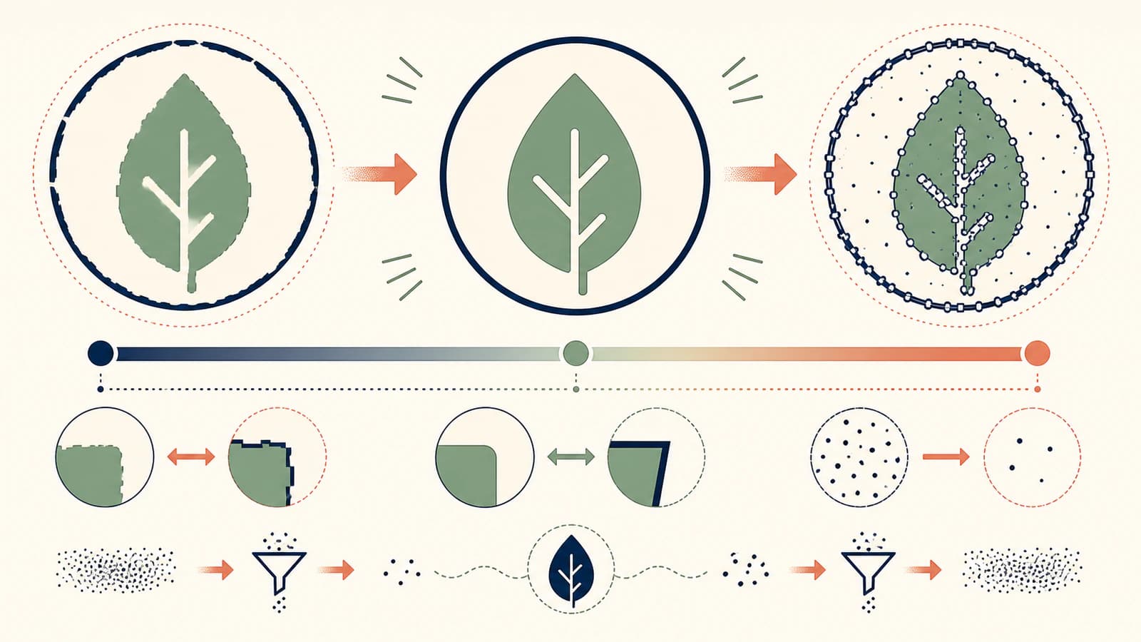
These controls cannot restore information that is absent from the source. If a tiny JPEG has rounded compression halos where a logo once had precise corners, the accurate fix is a better original or a manual redraw—not a more aggressive setting.
Clean the vectors before making toolpaths
After applying the trace, inspect the vector geometry without the bitmap covering it.
- Delete unwanted boundaries. A white background, crop edge, or shadow can become a large outer rectangle.
- Check thin lines for two contours. Boundary tracing follows both sides of a thick raster stroke. That may be correct for a filled shape but wrong for a single engraved line.
- Find open and overlapping contours. Vectric's Vector Validator is designed to find intersections, overlaps, and zero-length spans that can stop toolpath creation.
- Inspect nodes. Simple curves should not be made from dense, jittery point chains. Simplify only while the intended corner, gap, and silhouette stay intact.
- Check nesting and holes. Counters inside letters and other negative spaces need usable inner contours, not filled regions or loose duplicates.
- Confirm dimensions. Measure a known feature after import and again before calculating toolpaths.
The broader CNC vector preflight explains why closed contours, manageable nodes, and single rather than doubled lines matter downstream. If an SVG-to-DXF step creates hundreds of short segments, use the DXF segment diagnosis before blaming the machine.
When importing a cleaner SVG is faster
Trace inside VCarve when the source is simple, its important regions isolate cleanly, and the result needs little repair. Staying in one application is convenient, and the preview makes quick black-and-white work easy.
Use a vector prepared elsewhere when the source has several meaningful colors, the Trace Bitmap result contains too many tiny pieces, or you want to compare a second tracing method before cleanup. VCarve Pro's current documentation lists SVG among its supported imported vector formats, so you can do the reconstruction first and keep VCarve focused on drawing cleanup and CAM.
PerfectVector's SVG and DXF for CNC workflow is one route. Upload a supported raster, inspect the reconstructed color regions and paths, export SVG or DXF, then import the file into VCarve. This does not generate toolpaths, choose a cutter, or guarantee that every small detail can be machined. It gives you another vector result to audit.
Compare both traces on the same source. Keep the one that preserves the required silhouette and holes with fewer stray regions and less repair—not the one that merely has the most detail.
Assign and preview the CNC operation
Once the contours pass inspection, assign toolpaths according to the job: profile around a boundary, pocket an enclosed region, or use suitable geometry for V-carving. Do not infer machining settings from the image. Tool choice, depth, feeds, speeds, workholding, material, and safe machine operation belong to the actual CNC setup.
Preview the calculated toolpaths and check the cut direction, inside-versus-outside selection, start depth, final depth, tabs, and the features the cutter cannot physically reach. Run a representative test in inexpensive material before committing valuable stock.
FAQ
Where is Trace Bitmap in VCarve? Import and select the bitmap in the 2D view, then open Trace Bitmap in the vector-creation tools. In current Vectric help, the workflow is also described as fitting vectors to the selected bitmap.
What image formats can VCarve trace? Vectric's current VCarve Pro documentation lists BMP, JPG, TIF, GIF, and PNG for bitmap import. Check the documentation for your installed version if a file does not appear in the import dialog.
Why does my VCarve trace have two lines around every stroke? Trace Bitmap follows the boundaries of a visible region. A thick raster stroke has an inside and outside edge, so it commonly becomes two contours. Keep both for a filled shape or outline; create a centerline when the intended operation should follow one path.
How do I remove specks from a VCarve bitmap trace? Increase Noise Filter carefully and preview again. It removes small pixel regions, but too much can also erase punctuation, small holes, or narrow parts you meant to keep.
Does Trace Bitmap create G-code? No. It creates vector boundaries. You still need to inspect the geometry, assign the appropriate toolpaths, calculate them, preview the result, and post-process the job for the correct machine.
Sources
- Vectric — Trace Bitmap — Official tracing workflow, black-and-white and color controls, selected-area tracing, Corner Fit, Noise Filter, Preview, and Apply.
- Vectric — VCarve Pro documentation — Current bitmap and vector import behavior, supported vector formats, and the design-to-toolpath workflow.
- Vectric — Vector Validator — Official contour checks for intersections, overlaps, and zero-length spans.
- PerfectVector — SVG and DXF for CNC — First-party description of the alternative raster-to-vector workflow and supported CNC handoff formats.
If Trace Bitmap turns a simple image into a long repair job, compare a cleaner CNC vector, import it into VCarve, and keep the geometry that gives you the most reliable toolpath preview.
More from the blog

FreeCAD Image to Sketch: Build Editable Geometry
Choose the right FreeCAD image-to-sketch workflow: trace a scaled reference for exact CAD work, or convert suitable flat artwork to DXF and clean it up.

SolidWorks Image to Sketch: Choose the Right Route
Turn a SolidWorks Sketch Picture into useful geometry with Picture to Sketch, AutoTrace, manual reconstruction, or a DXF handoff, then verify the result.