Carbide Create Image Trace: Built-In or Clean SVG?
Compare Carbide Create Image Trace with importing a clean SVG. Learn when each route works and how to check closed paths, nodes, scale, and toolpaths.
On this page
- What Carbide Create Image Trace does
- A source that traces well
- Stop adjusting when the trace needs design work
- When importing SVG is the better route
- Audit the vectors before creating toolpaths
- Check closed paths
- Remove duplicate and stray geometry
- Use a sensible node count
- Verify size
- Separate geometry from toolpath intent
- Built-in trace versus clean SVG
- From vectors to a safer CNC check
- FAQ
- Sources
Carbide Create can trace an image into vectors and can also import SVG or DXF files. Its current product page describes automatic tracing as a CNC-focused way to make simple vectors that are easy to machine. It also supports direct SVG and DXF import when the design has already been prepared elsewhere. (Carbide Create)
Use the built-in Image Trace for a clean, high-contrast bitmap that needs little correction. Import a prepared SVG when the artwork needs exact lettering, controlled holes, deliberate centerlines, or more cleanup than you can verify quickly inside the trace workflow.
The quick choice
- Built-in trace: fastest for a simple black-and-white silhouette or badge.
- Clean SVG: better when path structure, exact curves, or repeatability matters.
- Either route: inspect closed geometry, duplicate edges, node density, and scale.
- Do not assign a toolpath until you know which boundary the cutter should follow.
- Simulate, check workholding and clearance, and follow the machine and cutter guidance before machining.
What Carbide Create Image Trace does
The tracing command turns visible raster regions into vector geometry. Carbide 3D says the function was designed for CNC routers and aims to create simple, clean vectors rather than connected application-specific shapes. The original staff announcement documented JPG and PNG input, black-and-white thresholding at launch, and grouped output that could be ungrouped for editing. (Carbide 3D community announcement)
That launch post is historical, so treat its interface details as context rather than a guarantee that every current control looks the same. The durable idea remains useful: tracing converts pixels into ordinary vectors, after which those vectors must be judged as machining geometry.
The official Image Tracing Comes to Carbide Create video demonstrates the feature's intended role. A short command sequence is only the start. Tool selection, depth, stock, workholding, zero, feeds, speeds, and machine limits remain separate CAM and setup decisions.
A source that traces well
The easiest inputs share a few traits:
- strong contrast between subject and background;
- flat shapes instead of soft shadows and gradients;
- enough resolution to describe curves without large pixel steps;
- no paper texture, compression blocks, or background clutter;
- features larger than the cutter and material can reproduce.
Preprocess the image before tracing if the preview includes dust, texture, or a gray shadow. Crop tightly, correct the contrast, and remove the background. Upscaling cannot recover missing detail, but a cleaner edge can help the tracer see the intended boundary rather than the defects around it.
Photos are a poor match for a compact 2D pocket or profile trace. If the goal is a relief, texture, or tonal engraving, choose the corresponding image or 3D workflow rather than forcing every shade into closed contours.
Stop adjusting when the trace needs design work
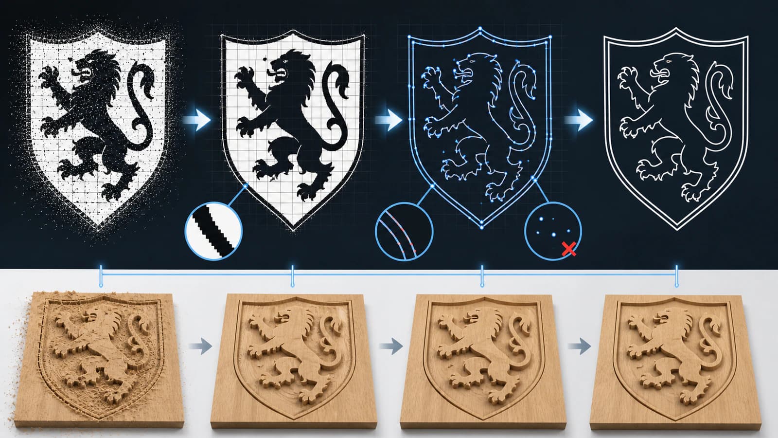
Tracing controls can improve threshold separation and curve fitting, but there is a point where another pass only trades one defect for another. Use this stop rule:
- Adjust the trace until the main silhouette and important holes are present.
- Inspect small identifying features at the intended physical size.
- If removing noise also deletes required geometry, stop.
- If smooth curves still contain repeated dents or excessive nodes, stop.
- Redraw the few critical shapes or prepare the vector outside Carbide Create.
This keeps a five-minute trace from turning into a long repair session. A prepared SVG is not automatically superior, but it gives you a broader cleanup environment before the geometry reaches CAM.
When importing SVG is the better route
Carbide Create's product page says SVG and DXF can be loaded directly, then used to create toolpaths. Import a clean SVG when you need:
- exact logo proportions or approved lettering;
- a known physical dimension or part interface;
- compound shapes with important interior holes;
- a single scoring or engraving centerline;
- repeated production from the same approved artwork;
- easier comparison with a source image before CAM.
PerfectVector's image-to-SVG tool for CNC can reconstruct a raster source before import. Check the result as geometry: compare the silhouette, inspect negative spaces, remove any embedded bitmap, and confirm that curves use a manageable number of nodes.
Keep the original design file and export a simplified delivery copy. Text should usually become outlines when the exact letter shapes matter, but remember that an outlined stroke becomes a closed band with two edges. That is not the same as one centerline engraving path.
Audit the vectors before creating toolpaths
Check closed paths
Pocket and profile operations usually need coherent boundaries. Zoom into joins and verify that endpoints meet. If a pocket selection leaks, fills an unexpected region, or cannot be selected as intended, inspect for a tiny gap or crossing segment.
Remove duplicate and stray geometry
Two identical vectors can look like one line and produce repeated motion. Delete hidden copies, isolated specks, and distant objects left from the trace. Ungroup the trace only when you need to select and clean its parts.
Use a sensible node count
More nodes do not mean more accuracy. Dense points can preserve pixel stair-steps and make edits awkward. Simplify gradually, compare against the source, and keep nodes where the curve changes direction. The SVG node cleanup guide gives a practical audit.
Verify size
Choose one feature with a known dimension and measure it after trace or import. Do this before toolpaths, tabs, or duplicated layouts. A visually correct shape at the wrong size is still the wrong part.
Separate geometry from toolpath intent
A vector boundary is not yet a cut instruction. Carbide Create's current product page describes pockets as clearing inside a vector and contours as cutting along the inside or outside. Decide which result the job needs, then select the correct geometry and toolpath.
Built-in trace versus clean SVG
| Decision | Built-in Image Trace | Prepared SVG import |
|---|---|---|
| Best starting source | Simple, high-contrast JPG or PNG | Approved artwork or a raster that needs structured cleanup |
| Setup time | Usually shorter | More preparation before import |
| Curve control | Limited to trace and vector editing workflow | Full control in the source vector workflow |
| Exact text and holes | Must be checked after trace | Can be deliberately built before import |
| Repeat production | Good after the trace is cleaned and saved | Good when an approved master and delivery copy are maintained |
| Final responsibility | Inspect geometry and toolpaths | Inspect geometry and toolpaths |
The two routes converge on the same preflight. Choose the one that reaches trustworthy geometry with less ambiguity.
From vectors to a safer CNC check
Carbide Create includes 3D simulation, which is useful for checking what selected toolpaths are expected to remove. Simulation does not verify real-world workholding, cutter condition, stock flatness, machine clearance, or a safe origin.
Before machining:
- Confirm stock dimensions and coordinate origin.
- Check tool diameter, flute length, and maximum depth against the operation.
- Review inside versus outside contour direction and pocket boundaries.
- Simulate every toolpath and look for missing or repeated regions.
- Check clamps, hold-downs, fixtures, and travel clearance.
- Use feeds, speeds, and depth guidance appropriate to the exact cutter, material, and machine.
- Run a controlled test or air-cut procedure when the setup warrants it.
The complete image-to-SVG CNC guide covers the path from source selection through CAM handoff in more detail.
FAQ
Can Carbide Create trace a JPG or PNG? Yes. Carbide 3D's official tracing announcement documented JPG and PNG input, and the current product page continues to list automatic image tracing as a Carbide Create feature.
Is Carbide Create Image Trace good for logos? It can work well for a clean, high-contrast logo. Check lettering, holes, and exact proportions. Use an approved SVG or rebuild critical shapes when the trace drifts.
Should I trace in Carbide Create or import SVG? Trace in Carbide Create for a simple source that needs little correction. Import a prepared SVG when you need deliberate path structure, exact curves, centerlines, or repeatable approved artwork.
Why does my Carbide Create trace have too many nodes? The source may contain pixel stair-steps, texture, compression noise, or low-contrast edges. Clean the bitmap first, simplify carefully, or reconstruct the artwork in a dedicated vector workflow.
Does a traced vector become a CNC toolpath automatically? No. The trace creates geometry. You still choose the tool, operation, depth, stock setup, feeds, speeds, and inside or outside relationship, then simulate and verify the job.
Sources
- Carbide 3D: Carbide Create — Current automatic tracing, SVG/DXF import, pocket/contour behavior, and simulation features.
- Carbide 3D Community: Carbide Create Image Tracing — Official staff launch details for input, thresholding, source size, grouping, and ordinary vector output.
- Carbide 3D: Image Tracing Comes to Carbide Create — Official feature overview and dated launch context.
If the built-in trace needs more repair than verification, prepare a clean SVG for CNC, import it into Carbide Create, and audit the geometry again before creating toolpaths.
More from the blog

Why DXF Files Have Too Many Segments for CNC Work
A DXF gets dense when source traces, exported curves, duplicate paths, or fragments become too many entities. Diagnose the cause, then clean it before CAM.

Convert an Image to SVG for Clean 3D Printing
A 3D printer can't extrude pixels, so flat designs start as an SVG. Here's how to turn an image into a clean, closed-path SVG that imports and extrudes the first time.