
SVG Relative Path Commands: Track the Current Point
Read absolute and relative SVG paths by tracking the current point. Test moveto pairs, closepath resets and cubic coordinates with an original matched example.
On this page
- Read positions and offsets separately
- Compare two descriptions of the same original artwork
- Follow the first m and its implicit lines
- Use the closed subpath's start for the next move
- Measure each cubic control from the same starting point
- Move artwork without confusing placement with path syntax
- Inspect source geometry before changing its notation
- FAQ
- Sources
Absolute SVG path commands such as M, L and C use positions in the current user coordinate system. Their relative forms, m, l and c, use offsets from the current point. To read or rewrite a path, track that point after each segment. Changing a command letter without changing its numbers can change the shape.
Two rules cause much of the confusion: the first pair of an initial m acts as an absolute move, while additional pairs are relative lines; and Z or z closes a subpath and resets the current point to its start. A new relative move after that closure uses the reset point.
Read positions and offsets separately
The W3C path specification defines a path through its current point, subpaths and drawing commands. The coordinates are SVG user units, not necessarily screen pixels. A viewBox or transform can map them to a different displayed position.
Starting at (40, 40), these two commands describe the same line:
L180 40
l140 0
The first specifies the endpoint (180, 40). The second adds (140, 0) to (40, 40). Both finish at (180, 40), which becomes the current point for the next segment.
By contrast, l180 40 adds (180, 40) and finishes at (220, 80). The command is valid syntax, but it draws a different line.
| Command | Meaning of its position values |
|---|---|
| M x y | Begin a subpath at the specified position |
| m dx dy | Begin a subpath relative to the current point, with the initial m behavior below |
| L x y | Draw a line to a position |
| l dx dy | Draw a line to the current point plus an offset |
| C / c | Specify two controls and an endpoint, as positions or same-start offsets |
| Z / z | Close to the subpath start and reset the current point |
Uppercase and lowercase Z have the same effect: they take no coordinate arguments. The MDN d reference lists the commands and their individual parameters.
Compare two descriptions of the same original artwork
Save this complete SVG as absolute.svg and open it in a browser. It contains a compound teal badge with a square hole and a separate coral cubic curve:
<svg xmlns="http://www.w3.org/2000/svg" width="300" height="240" viewBox="0 0 300 240">
  <path class="badge" fill="#173b40" fill-rule="evenodd" d="M40 40L180 40L210 80L180 140L40 140Z M80 70L80 110L120 110L120 70Z"/>
  <path class="curve" fill="none" stroke="#f28567" stroke-width="6" d="M40 190C80 145 155 225 220 180"/>
</svg>
For relative.svg, keep the SVG size, viewBox and styles, but replace the two path elements with these:
<path class="badge" fill="#173b40" fill-rule="evenodd"
  d="m40 40 140 0 30 40 -30 60 -140 0z m40 30 0 40 40 0 0 -40z"/>
<path class="curve" fill="none" stroke="#f28567" stroke-width="6"
  d="m40 190c40 -45 115 35 180 -10"/>
We rendered both original files in a browser, alongside a deliberately broken copy of the absolute badge. The broken copy changes only its first L180 40 to l180 40; the numbers remain unchanged.
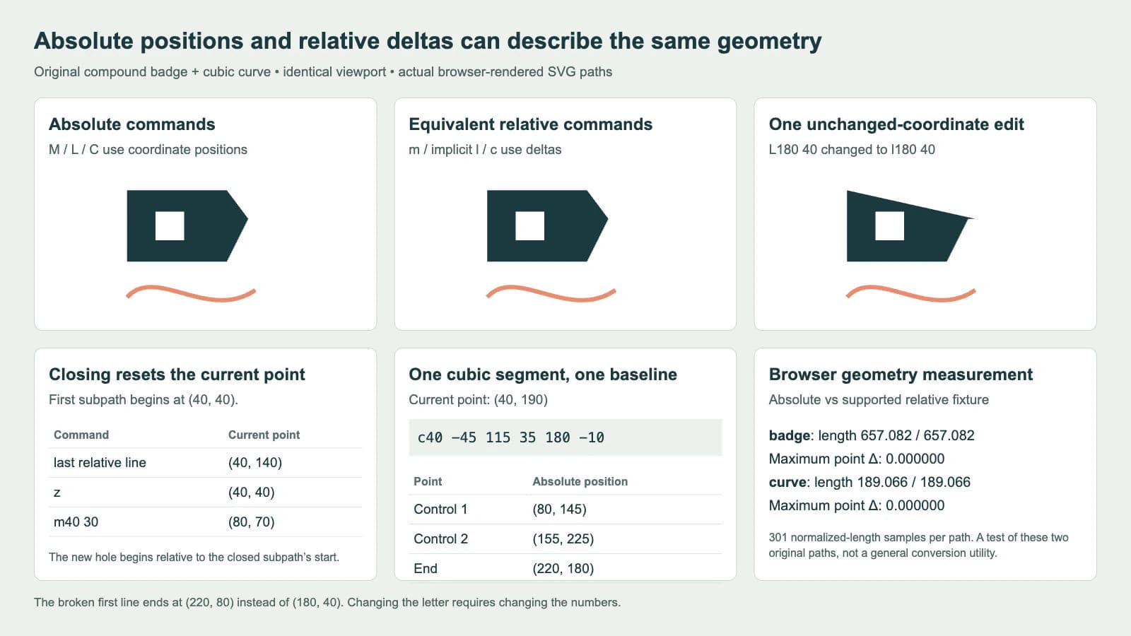
Our page used native SVG getTotalLength() and getPointAtLength() to compare 301 samples per path at corresponding fractions of total length. The displayed lengths were 657.082 user units for each badge and 189.066 for each curve. The maximum sampled point difference displayed as 0.000000 for both pairs.
That measurement corroborates these specific strings, whose line vertices and cubic points also match by the arithmetic below. It is not proof that an arbitrary rewrite or converter handles every SVG command. The comparison uses the same untransformed viewport and paint settings throughout.
Follow the first m and its implicit lines
Our badge starts with:
m40 40 140 0 30 40 -30 60 -140 0zOnly the first pair performs a move. The remaining pairs behave as implicit relative l segments. The moveto definition explicitly keeps those later pairs relative even though the initial m40 40 is treated as an absolute start.
Track one pair at a time:
| Pair or command | Operation | Current point afterward |
|---|---|---|
| m40 40 | Initial move | (40, 40) |
| 140 0 | Implicit relative line | (180, 40) |
| 30 40 | Implicit relative line | (210, 80) |
| -30 60 | Implicit relative line | (180, 140) |
| -140 0 | Implicit relative line | (40, 140) |
| z | Close to this subpath's start | (40, 40) |
For comparison, a multi-pair uppercase M would turn its later pairs into implicit absolute L segments. It would not treat every pair as another move, and it would not use the same deltas as this lowercase example.
A path element establishes its own path sequence. Do not start its initial relative m from the endpoint of an unrelated preceding path element.
Use the closed subpath's start for the next move
The hole begins after the first z:
m40 30 0 40 40 0 0 -40zAt that moment the current point is (40, 40), so the new relative move adds (40, 30) and starts the hole at (80, 70). Its implicit lines then reach (80, 110), (120, 110) and (120, 70) before closing.
If you mistakenly used the outer badge's last line endpoint (40, 140) as the baseline, you would place that move at (80, 170). The earlier closure is what makes that calculation wrong. The closepath definition resets the current point to the initial point of the current subpath.
Both subpaths belong to one path element. Its fill-rule="evenodd" makes the inner square an opening in this fixture. Keep the fill rule and paint settings stable when comparing coordinate rewrites, so a fill change does not obscure the geometry you are testing.
Measure each cubic control from the same starting point
The separate curve starts at (40, 190):
M40 190 C80 145 155 225 220 180
m40 190 c40 -45 115 35 180 -10
For this one lowercase c segment, all three pairs are offsets from (40, 190). The second control is not measured from the first control, and the endpoint is not measured from the second.
| Point | Relative pair | Absolute position |
|---|---|---|
| First control | (40, -45) | (80, 145) |
| Second control | (115, 35) | (155, 225) |
| End | (180, -10) | (220, 180) |
After the segment, update the current point to its endpoint (220, 180). A following relative segment would use that new start. The MDN paths tutorial explains the cubic controls and absolute/relative forms; the Bézier join guide separately covers tangent handles and the shorthand S command.
Do not generalize coordinate subtraction to every number in every command. In an arc, the radii, rotation and flags have different jobs; only its endpoint pair switches between absolute and relative positions. Consult the arc flag explanation before rewriting A or a data. This example demonstrates lines, moves, closure and one ordinary cubic segment rather than a general path conversion routine.
Move artwork without confusing placement with path syntax
For this fully relative compound badge, changing its initial m40 40 to m60 60 shifts its vertices by (20, 20): the later deltas and relative subpath move follow that changed start. It leaves the separate curve path untouched. In mixed data, later absolute positions also stay anchored to their specified coordinates, so editing the first move can deform the path.
To move the whole two-path artwork as one unit, keep both d strings and place their elements inside a group with transform="translate(20 20)". The SVG coordinate-system specification explains how transforms establish coordinate mappings. A group transform changes placement without rewriting the original path data.
Check that the viewport still contains the moved artwork; translating a group does not automatically enlarge its canvas. The SVG transform-order guide covers placement when translation and scale are combined.
Inspect source geometry before changing its notation
PerfectVector can help when the artwork exists only as a PNG or JPG. Prepare an SVG candidate, then compare its recovered silhouette, holes and curve shape with the source before editing its path data. Absolute or relative notation does not establish whether the recovered geometry is suitable.
Use an available vector master directly, or redraw a simple symbol when that is easier to control. Rewriting commands cannot recover the intended shape from missing raster information. The image-vectorization overview explains that separate reconstruction step.
When editing a usable SVG, keep a copy of the original, change one supported segment at a time, and compare the actual file at matching scale. Track the subpath start as well as the current point. Preserve fill and stroke settings during the comparison, then test the exported file in its receiving application.
FAQ
Is the first lowercase m relative to another path? No. When m is the first command of a path, its first pair is treated as an absolute start. Additional pairs are implicit relative lines, and another path element's endpoint is not its starting baseline.
Where is the current point after Z or z? At the start of the subpath that just closed. A following relative move uses that reset point, not the endpoint of the preceding line.
Can I convert a path by lowercasing its commands? No. Position values must be recalculated for each command's semantics. This example's L180 40 becomes l140 0 from the current point (40, 40), while l180 40 draws a different line.
Sources
- W3C — SVG 2 Paths — Defines current points, initial moveto, implicit lines, closure and cubic parameters.
- MDN — Paths tutorial — Illustrates absolute and relative line and curve commands.
- MDN — d attribute — Lists command parameter roles, including arcs and closepath.
- W3C — SVG 2 Coordinate Systems — Explains user coordinate mappings and transform-based artwork placement.
Starting with raster-only artwork? Prepare SVG paths with PerfectVector, inspect the recovered silhouette and openings, then edit only the commands you understand and verify the delivered SVG against the original.
More from the blog
Graphviz SVG Images: Keep Node Artwork Portable
Add SVG artwork to a Graphviz node, inspect its image reference, and test a complete asset bundle against a moved diagram and a self-contained delivery copy.

Matplotlib SVG: Keep Plot and Logo Artwork as Paths
Export your Matplotlib plot as SVG, compose separate logo paths with svgutils, and check the delivered file for embedded pixels, placement, and font changes.