
SVG Morph Animation: Match Paths Before You Animate
Prepare SVG paths for a shape morph by checking command structure, corner order, and holes. Test an original example at the start, midpoint, and finish.
On this page
SVG morph animation changes a shape's geometry between two states. For native interpolation of path data, prepare matching command structures and decide which points should correspond. Two attractive endpoint drawings can still produce a collapsed or twisted shape halfway through.
W3C's path-data animation rules require the same number and types of commands in the same order for smooth interpolation. That is a structural requirement. It does not decide which corner of a logo ought to become which corner of its next state.
Start with a small pair you can inspect. The original examples below use a square, a diamond, and a deliberately reversed square to separate those two decisions.
Build two paths with corresponding corners
This hand-authored square and diamond both use M L L L Z: move to the first corner, draw three lines, and close the shape. Each coordinate pair has a matching position in the other path.
<svg id="matched" viewBox="0 0 160 160"
  xmlns="http://www.w3.org/2000/svg"
  role="img" aria-label="Square morphing into a diamond">
  <path fill="#147d78" d="M30 30L130 30L130 130L30 130Z">
    <animate attributeName="d" dur="2s" begin="0s"
      fill="freeze" calcMode="linear"
      values="M30 30L130 30L130 130L30 130Z;M80 20L140 80L80 140L20 80Z" />
  </path>
</svg>
The SVG animate element changes an attribute over time. Here it changes d over two seconds. The animation's fill="freeze" retains its final state; the path's green fill is a separate paint setting.
Keep the example in a standalone HTML page while inspecting it. It begins automatically without the inspection script below. For production controls, decide when it should play and provide a static state appropriate to the interface.
The corner mapping is explicit:
| Position in the path | Square | Diamond |
|---|---|---|
| First corner, after M | Upper left, 30 30 | Top, 80 20 |
| Second corner | Upper right, 130 30 | Right, 140 80 |
| Third corner | Lower right, 130 130 | Bottom, 80 140 |
| Fourth corner | Lower left, 30 130 | Left, 20 80 |
Both outlines travel around their perimeter in the same direction. The first corner moves toward the top of the diamond, the second toward its right, and so on. This is an authored design choice, not an interpretation of what either shape means.
Pause the actual interpolation
Inspect the start, midpoint, and finish before adjusting easing or adding decorative effects. For the SVG above, this helper pauses its timeline and seeks to a time in seconds:
const svg = document.querySelector('#matched');

function showMorphAt(seconds) {
  svg.pauseAnimations();
  svg.setCurrentTime(seconds);
}

showMorphAt(1); // Midpoint of the two-second animation
MDN documents pauseAnimations() and setCurrentTime() for controlling the SVG timeline. Connect the helper to buttons with values 0, 1, and 2. These are three positions in one interpolation, not three replacement drawings.
At one second, linear interpolation places each coordinate halfway between its two endpoint values. The first corner is therefore at 55, 25. The complete midpoint in this original example is:
M55 25L135 55L105 135L25 105ZWe checked this native SVG animation in a browser at the start, midpoint, and finish, then played it once. The midpoint remained a filled quadrilateral, and playback reached the diamond. That observation applies to these hand-authored paths in the tested browser; it is not a PerfectVector conversion result or a compatibility test across browsers.
Equal command counts can still produce a bad morph
Keep the starting square, but reverse the target square's corner order:
Start:  M30 30L130 30L130 130L30 130Z
Target: M30 30L30 130L130 130L130 30Z
The two endpoints look like the same square. Both strings still use M L L L Z. Yet the second and fourth corners now travel across the shape to swap places. At the midpoint, their coordinates coincide:
M30 30L80 80L130 130L80 80ZAll four points lie on a diagonal. In our browser test, the filled square collapsed to that diagonal at halfway and returned to a square at the end. Matching command structure made interpolation possible; matching the wrong points made the result undesirable.
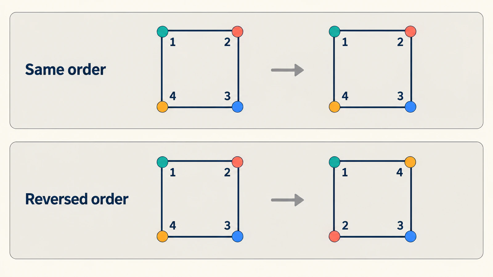
When an exported pair twists, inspect the first point and travel direction in each path. Then check whether corners and curve features occupy corresponding positions. Adding nodes indiscriminately can make this harder to see. The node cleanup guide helps simplify static artwork, but preserve the correspondence you established across both states.
Keep holes and separate pieces accounted for
A logo may contain an outer boundary, an opening, and a detached accent. Treat those as parts that need deliberate partners in the next state. Before animating, list which part changes into which. If one state has a hole and the other does not, decide how the opening should disappear instead of assuming a matching node count will settle it.
The fill-rule reference explains how SVG decides which regions are inside a path. Preserve the intended fill behavior while preparing and testing a compound path. If the opening already looks wrong in a static endpoint, use the filled-hole troubleshooting guide before adding a transition.
A practical inspection order is:
- Confirm each endpoint's silhouette, holes, and detached details.
- Identify the corresponding subpaths or separate elements.
- Align their starting points, direction, and useful features.
- Check intermediate states for crossed boundaries or vanishing details.
- Adjust timing only after accepting that geometry.
Separate elements can be easier to control when a small accent should fade or move independently. That choice is part of the animation design; it need not be forced into a single compound path.
Check the rules of your animation mechanism
The native example deliberately uses matching commands. A library can perform additional preparation, so its requirements may differ.
GSAP's MorphSVG documentation describes converting path data to cubic curves and adding points when needed. It also exposes mapping controls such as shapeIndex. Use those controls to review correspondence rather than assuming two independently exported shapes already match.
KUTE.js documents a different preparation model in its SVG Morph guide, including a separate workflow for subpaths. Check the version and component you actually use before applying native path restrictions or another library's advice to it.
Choose a small representative pair for that mechanism and inspect its intermediate geometry. A successful square-to-diamond test does not establish the behavior of a detailed compound logo. Keep a copy of the source artwork so you can distinguish changes introduced during animation preparation from the original design.
Prepare raster artwork before matching the states
If the vector master is missing and only PNG or JPG artwork remains, PerfectVector's image-to-vector workflow can help prepare an editable SVG candidate. Compare the silhouette, holes, and separate regions with the source, then inspect the downloaded paths. The SVG editing guide covers the next cleanup step.
Vectorizing two pictures does not establish semantic correspondence between their points or create a finished morph. Accept each static drawing first, then prepare the pair for the chosen animator. If an editable vector master already exists, work from it rather than retracing a raster copy.
Test a midpoint after every meaningful change to the pair. A simpler endpoint is useful only if the transition still follows the intended features. The blog's editing articles provide related source-preparation guidance.
FAQ
Do SVG paths need the same number of points to morph? For native path-data interpolation, matching command structure matters, including command types and order. A library may normalize different structures, so check its own documentation rather than relying only on point count.
Why does my SVG morph twist even when the endpoints look correct? The points may correspond in an unwanted order. Check the start point, direction, and feature matching, then inspect the midpoint. Identical endpoint silhouettes can hide a collapsed intermediate shape.
Can two separate SVG files be morphed automatically? An animator needs compatible or normalized geometry and a useful mapping between states. Two file extensions alone do not supply that mapping; inspect paths, holes, and separate pieces.
Does converting two PNGs to SVG create a matched morph pair? No. Conversion prepares static vector candidates. You still need to match their parts and points, choose an animation mechanism, and inspect the transition.
Sources
- W3C — SVG paths — defines native path-data interpolation structure and parameter matching.
- MDN — animate — documents attribute animation over time.
- MDN — pauseAnimations — supports pausing the inspection timeline.
- MDN — setCurrentTime — documents seeking the SVG timeline in seconds.
- MDN — fill-rule — explains interior-region behavior for compound artwork.
- GSAP — MorphSVG — describes normalization and point-mapping controls.
- KUTE.js — SVG Morph — documents its component-specific preparation and subpath workflow.
Match the parts and inspect the midpoint before polishing the timing. If your starting artwork is raster, prepare an SVG candidate, verify its static geometry, and then build the corresponding animation states.
More from the blog
Unreal Engine SVG Import: Check Motion Design Geometry
Prepare an SVG for Unreal Engine Motion Design, inspect holes and separate pieces, and distinguish scene geometry from a texture or runtime UI image workflow.
FontForge SVG Import: Turn Drawn Shapes Into Glyph Outlines
Import SVG artwork into a FontForge glyph slot, then check contours, baseline, scale, and spacing. Learn what tracing provides and what still needs font design.