
SVG Markers: Build Custom Arrowheads That Stay Aligned
Build a custom SVG arrowhead, align its tip, reverse the start marker, and compare sizing at two stroke widths with an original browser-rendered example.
On this page
To attach a custom arrowhead to an SVG path, define its artwork inside a <marker> and reference its ID with marker-end. Set refX and refY to the point on the artwork that should meet the path endpoint. Then choose whether the marker should rotate with the path and grow with its stroke width.
Those choices solve different problems. An arrow can point in the right direction and still miss its endpoint. It can also line up correctly on a thin stroke, then become too large when the line gets heavier. This walkthrough separates placement, direction, and size using one original pointer shape.
Start with a small, complete SVG
Save the following as markers.svg and open it in a browser. The pointer is a hand-authored example, with its tip at (11, 6) inside a 12 × 12 coordinate space. It is not a PerfectVector conversion result.
<svg xmlns="http://www.w3.org/2000/svg" viewBox="0 0 400 180">
  <defs>
    <marker id="pv-pointer" viewBox="0 0 12 12"
      refX="11" refY="6" markerWidth="6" markerHeight="6"
      markerUnits="strokeWidth" orient="auto-start-reverse">
      <path d="M1 1 L11 6 L1 11 L4 6 Z" fill="#087f82"/>
    </marker>
  </defs>
  <g fill="none" stroke="#20364d" stroke-width="4"
    marker-start="url(#pv-pointer)" marker-end="url(#pv-pointer)">
    <path d="M50 45 H350"/>
    <path d="M50 135 C130 75,260 195,350 135"/>
  </g>
</svg>
The first path is straight; the second is a curve. Both reference the same marker at both ends. The <defs> block stores the definition, while the path references make it visible. MDN's marker reference covers the start, middle, and end attachment properties.
Use an ID that is unique in the containing document. If you combine several SVGs inline, prefix their marker IDs and update every matching url(#...) reference. The SVG symbol sprite guide explains the same reference-management problem for reused icons.
Put the intended point on the endpoint
refX="11" refY="6" says which point of the marker artwork should coincide with the path's endpoint. It does not move the path itself. In this example, that point is the sharp tip.
Compare that with refX="0" refY="0". The browser places the marker's coordinate origin on the endpoint, leaving the tip farther right and lower down on a horizontal line. Increasing the marker size makes the error more visible; it does not repair the anchor.
MDN documents refX and refY as the marker's reference-point coordinates. Read them against the artwork's own coordinates, including its viewBox, rather than guessing from its displayed width.
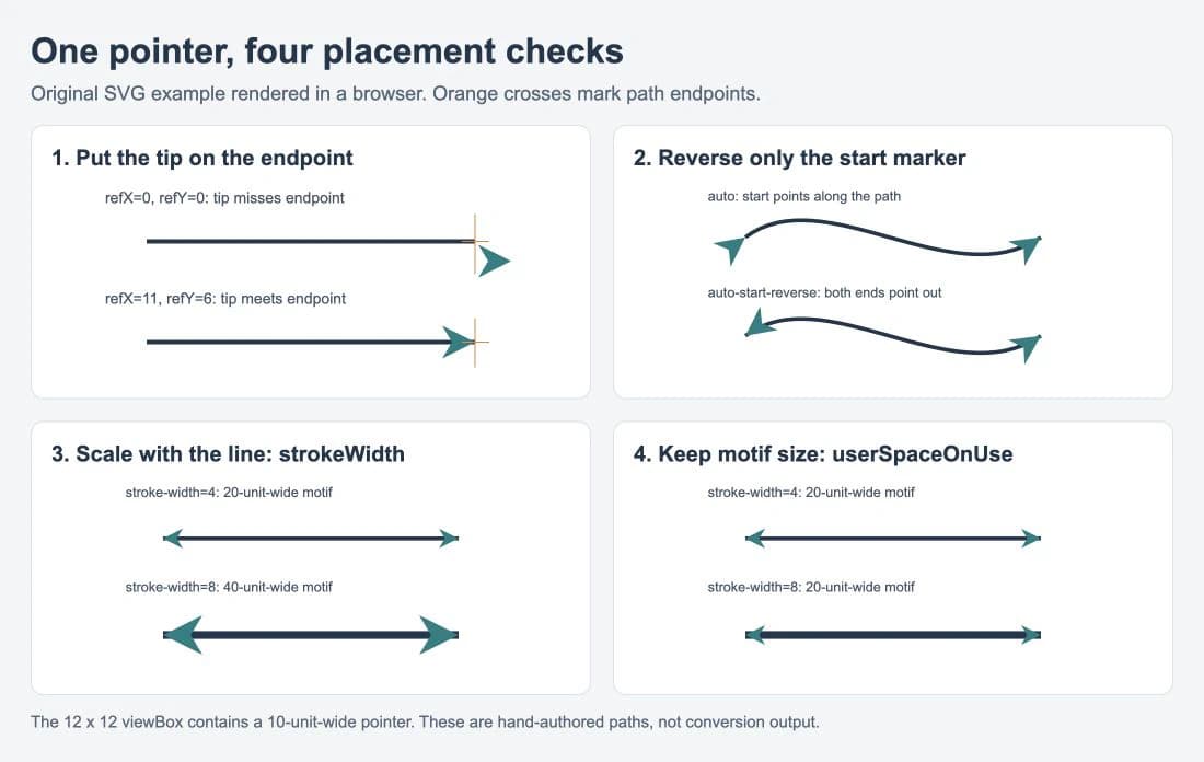
We opened the complete SVG separately and rendered the comparison in a browser. Changing the reference point brought the tip onto the orange cross. Changing the orientation reversed the start arrow. Changing the unit mode controlled whether the pointer grew with the line. These observations apply to this example; inspect the actual exported file in the application that will receive it.
A tip anchored exactly at the endpoint also leaves the stroke extending all the way to that point. On a thick line, part of the stroke can remain visible beside a narrow tip, as the comparison shows. If that seam matters, adjust the motif, the anchor, or the path endpoint together and inspect the join. Marker placement does not trim the underlying stroke.
Let the curve control direction
For an arrowhead at the end of a path, orient="auto" follows the path's direction at that point. A curve's ending direction comes from its local tangent, so the arrow need not point toward the straight-line direction between the path's two endpoints.
For arrows at both ends, use orient="auto-start-reverse". It behaves like auto at the end but rotates the start marker by an additional 180 degrees. MDN's orient documentation describes this as the way to reuse one arrowhead that points outward from both ends.
The top-right comparison makes the difference visible: with auto, the start pointer faces along the curve. With auto-start-reverse, it faces away from the start. You do not need a second, manually flipped copy of the shape.
Check path direction when the result surprises you. Reversing a path changes which end is its start. An arrow intended to indicate flow should be attached according to that direction, even if the two ends happen to occupy the same screen positions as before.
Decide whether line weight should change marker size
markerUnits sets the coordinate system used for the marker's dimensions and contents. Its default is strokeWidth; the alternative is userSpaceOnUse. See MDN's markerUnits reference for the distinction.
| Choice | When the stroke changes from 4 to 8 | Useful when |
|---|---|---|
strokeWidth | Marker dimensions double | The arrowhead should keep its proportion to line weight |
userSpaceOnUse | Marker dimensions stay the same in the referencing element's user coordinates | The motif should keep its size across different line weights |
The pointer spans 10 of the 12 horizontal units in its viewBox. With markerWidth="6" and markerUnits="strokeWidth", its unrotated width is 10 / 12 × 6 × stroke-width: 20 user units on the 4-unit stroke and 40 on the 8-unit stroke. The bottom-left comparison uses those settings.
To keep that pointer 20 units wide at both stroke weights, change the definition to:
markerUnits="userSpaceOnUse" markerWidth="24" markerHeight="24"The bottom-right comparison uses those values. Keeping markerWidth="6" while changing only the unit mode would produce a much smaller pointer, because six units would no longer be multiplied by the stroke width.
userSpaceOnUse does not mean a fixed number of screen pixels. Scaling the surrounding SVG or its coordinate system can still change the displayed size. Inspect the marker at the final layout size, especially when a large motif is being reduced to a small diagram annotation.
Prepare a custom motif before making it a marker
For a triangle or simple pointer, draw the path directly. For existing vector artwork, keep the original paths and decide which coordinate should attach to the line. Preserve intentional holes, simplify details that disappear at the intended size, and give the artwork enough space inside the marker viewport.
If a custom arrowhead or decorative motif survives only as a PNG or JPG, PerfectVector's image-to-vector workflow can help recover an SVG candidate before this packaging step. Compare the silhouette and small openings with the source, remove any unwanted background shape, then choose the approved artwork's bounds and anchor point. Conversion does not create marker definitions, assign path direction, or add diagram connector behavior.
Keep colors explicit while testing. This example uses a teal marker and a navy line so their boundary remains visible. If your own arrow should have one color throughout, set both paints deliberately and inspect the delivered result. The SVG color-editing guide covers fixed fills and styles that can interfere with recoloring.
Check the file where it will be used
Keep an editable master, then test a delivery copy through the actual website, editor, or export workflow. A correct browser preview establishes the browser appearance of that file; it does not establish every application's import behavior.
- Confirm each
url(#...)points to the intended marker ID after packaging or optimization. - Check straight and curved paths, including a start marker if you use one.
- Compare the thinnest and heaviest line weights in the design.
- Inspect the tip, join, and any clipped artwork at the final display size.
- Reopen the delivered SVG independently and compare it with the source preview.
Markers are visible decorations attached to path positions. They do not create semantic connections between diagram objects. For a diagram editor's own connection points and stencil behavior, use its native shape system; the draw.io custom-shape guide covers that separate task.
A marker is also not automatically a physically joined cutting outline. If the destination needs closed cut geometry, prepare and inspect a separate path-based delivery copy in a vector editor. A line and arrowhead that overlap on screen are not proof of a united contour. More SVG preparation guides cover artwork cleanup and downstream checks.
FAQ
Why is my SVG arrowhead offset from the line? Check refX and refY against the marker artwork's coordinates. They identify the point placed on the path endpoint. In this example, the tip is at 11,6; using 0,0 places the origin there instead.
How do I reuse one arrowhead at both ends? Reference the same marker with marker-start and marker-end, and use orient="auto-start-reverse". The start instance reverses while the end instance follows the path direction.
Why does my arrowhead grow when I thicken the line? The default markerUnits value is strokeWidth. Use userSpaceOnUse when the marker should keep its size in the element's user coordinates, then adjust markerWidth and markerHeight for that unit system.
Does a marker turn the arrow into one closed path? No. The marker definition remains separate from the path that references it. Prepare and inspect actual joined geometry if a downstream cutting or editing workflow requires it.
Sources
- MDN — marker — marker definitions, supported shapes, and attachment properties.
- MDN — refX — horizontal reference-point placement in the marker coordinate system.
- MDN — refY — vertical reference-point placement in the marker coordinate system.
- MDN — orient — automatic rotation and reversal of the start instance.
- MDN — markerUnits — stroke-relative sizing and user-coordinate sizing.
Start with one motif and check its anchor, direction, and size on both a line and a curve. If your own motif exists only as a raster image, prepare an SVG candidate, inspect its silhouette and openings, then package the accepted paths as a marker.
More from the blog
Inline SVG vs img: Choose How Your Artwork Behaves
Compare the same SVG as an image and inline markup. Test CSS color control, sizing, accessible names, and reuse before choosing how to embed your artwork.
SVG Gradient Units: Share One Blend Across Logo Paths
Make a gradient flow across separate SVG logo paths. Compare gradientUnits, set shared endpoints, and fix a translated group's unexpected color shift.