
Stitch Large Drawing Scans Before Vectorizing
Join overlapping artwork sections into one raster before tracing. Match several landmarks, check a crossing stroke, and catch offset or scale errors early.
On this page
Stitch the overlapping sections of a large drawing into one raster image before vectorizing. Use shared landmarks to check alignment, choose which section supplies the overlap, then inspect a stroke crossing the join. Matching one point is insufficient: another point can still drift, or a line can jump at the seam.
The fixed-offset method below suits sections that already share orientation and scale. It moves one image across a canvas without rotating or stretching it. If your scans have scale, rotation, perspective, or paper-tone differences, resolve those separately or recapture the artwork before accepting the stitch.
The join has to pass before the trace
Preserve the original sections. Verify more than one landmark, inspect the crossing stroke in the saved composite, and check the whole image for clipped or duplicated artwork. A vectorizer can follow a bad join as faithfully as a good line.
Check whether the sections can share one canvas
An overlap is the part of the drawing visible in both images. A landmark is a recognizable point within that shared area, such as a corner, junction, or small isolated mark. Use distinct features already present in the artwork; a repeating grid can make the wrong match look plausible.
Keep untouched copies of every section. Export working PNGs at their existing pixel dimensions, and note which sides overlap. Do not independently resize a section just to make its displayed size convenient.
| Symptom in the overlap | What to investigate | Acceptance check |
|---|---|---|
| All inspected landmarks need the same horizontal and vertical move | Position offset | One translation aligns all of them |
| One point aligns but a distant point drifts | Scale, rotation, distortion, or an incorrect match | Several separated points agree after the underlying problem is resolved |
| Lines align but the page changes brightness | Paper tone or exposure | Inspect the seam without hiding or deleting pale ink |
| Only a tiny ambiguous overlap remains | Insufficient shared detail | Obtain another section or a different capture |
For the earlier capture decision, see scanning versus photographing line art. This guide starts with image sections you already hold and tests their assembly.
Match multiple landmarks before pasting
For a translation, record the same landmark's pixel coordinates in each image. Coordinates here use the top-left corner as (0, 0), with x increasing rightward and y increasing downward. Subtract the right-image coordinates from the left-image coordinates to find where the right tile would sit on a canvas anchored at the left tile.
Our original digital example has two deliberately distinct landmarks in a 200-pixel overlap:
| Landmark | Position in left tile | Position in right tile | Suggested right-tile origin |
|---|---|---|---|
| Red square center | (460, 162) | (40, 162) | (420, 0) |
| Blue circle center | (555, 420) | (135, 420) | (420, 0) |
Both give the same move. They are separated vertically and horizontally, so the second checks more than the first point alone. Also inspect a line through the overlap and features beyond it; two matches do not prove that arbitrary distorted scans are globally correct.
On your own sections, use an image viewer or editor that reports pixel coordinates. If the suggested offsets disagree, recheck that you picked corresponding points. If they still disagree, stop this simple translation recipe. Correct the capture geometry with a suitable registration workflow, or recapture; do not stretch a small region until one junction looks right.
Composite aligned sections with ImageMagick
You need the original sections, working PNGs, their dimensions and placement, and ImageMagick 7 for the tested commands. The following numbers belong to our controlled example, not a preset for every large drawing.
- Name the working tiles. Here,
left.pngis 620 × 600 pixels andright.pngis 580 × 600 pixels. Keep these inputs unchanged. - Choose the canvas extent. The left tile starts at
(0, 0). The right tile starts at(420, 0)and ends at x420 + 580 = 1000. Both are 600 pixels tall, so the canvas is 1000 × 600. For other nonnegative placements, include the full width and height of every placed tile. - Paste in a deliberate order. This command first places the left image, then the right image over it:
magick -size 1000x600 xc:white -gravity NorthWest -compose Over left.png -geometry +0+0 -composite right.png -geometry +420+0 -composite stitched.pngImageMagick's geometry reference describes offsets and command processing. Its command-line options document the compositing operator. The explicit NorthWest gravity anchors the placement to the top-left; +420+0 moves the right tile 420 pixels right and zero down.
- Know which pixels win. The example uses opaque PNGs. With Over compositing, the right tile supplies the overlap, including its white background. This is a hard ownership choice, without automatic alignment or seam blending. If the right section obscures a better left-section detail, choose a different seam or use a carefully edited mask in a layered workflow instead.
- Reopen
stitched.png. Check the full frame for clipping, then inspect the overlap at 100% zoom and enlarged. Keep the sections alongside the composite until it passes.
For real scans, a visible paper-tone boundary may need separate adjustment. Do not blur across a doubled line to disguise misalignment. Fix the geometry first, and use the TIFF source-cleanup checks when retouching would threaten faint ink or small gaps.
What the saved join showed
We authored an asymmetric 1000 × 600 drawing, split it into the two known-origin tiles above, and ran the composite command. The saved correct composite matched every source pixel. Both landmark centers stayed in place, and the black stroke continued across the join without a step.
These were original digital tiles with identical sampling and paper tone. No physical scanner, phone, native graphical editor, automatic registration, or PerfectVector conversion was tested. The exact pixel match establishes this known-offset operation only.
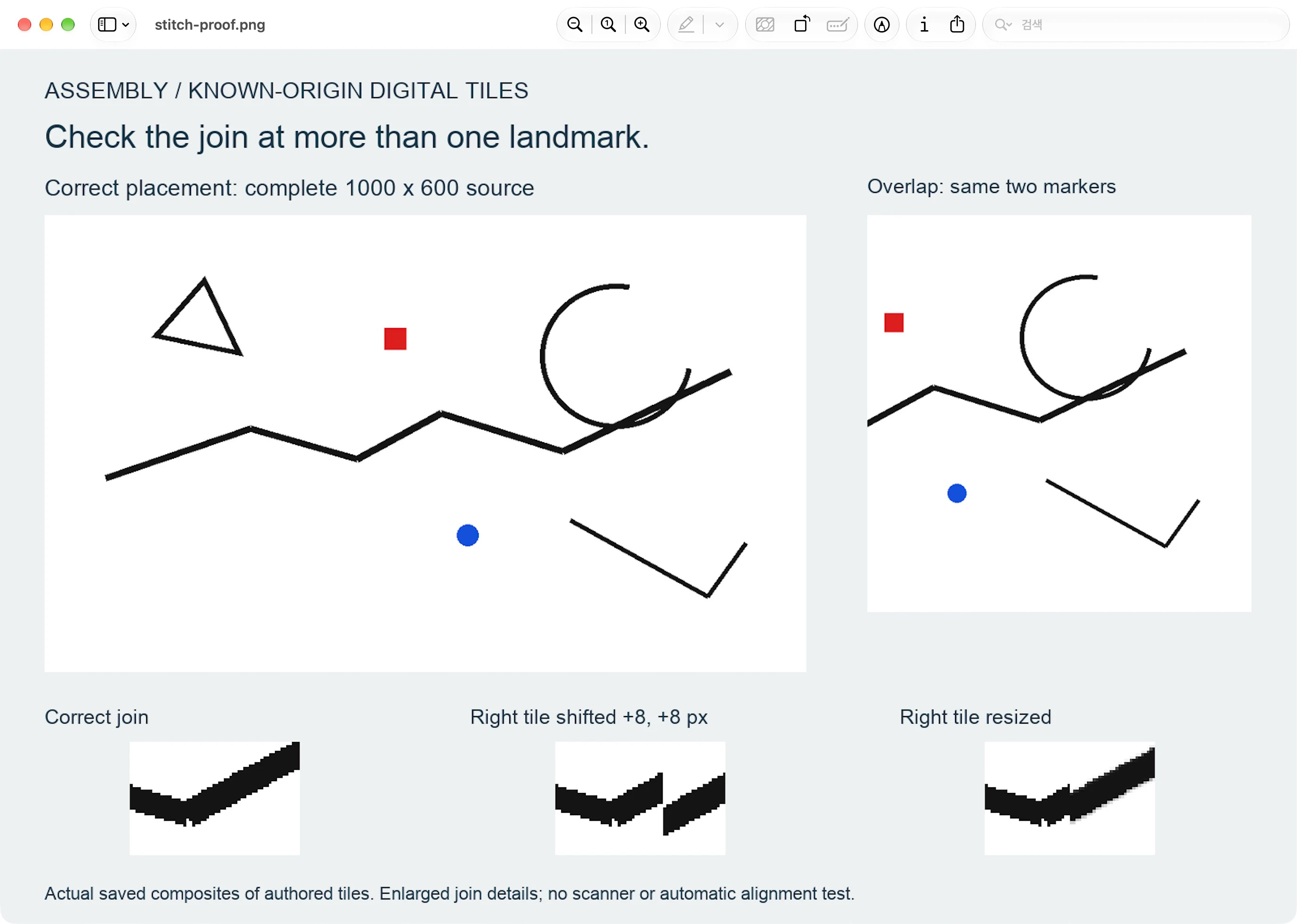
We retained two deliberately wrong outputs:
- Wrong offset: placing the right tile at
(428, 8)shifted both landmarks by eight pixels in each direction. The stroke jumped where the right tile began. - Wrong scale: resizing the right tile to 586 × 606 before placing it at
(420, 0)caused different landmark errors. The red center moved from(460, 162)to about(460.5, 163.5); the blue center moved from(555, 420)to about(556.45, 424.04).
Those unequal residuals are why nudging a resized tile until one point aligns does not establish the second point. The numbers describe our deliberately changed tile, not typical scanner error or a promised tolerance.
Accept or rebuild the assembly
Before tracing, inspect the saved raster against every original section:
- A stroke crossing the seam has no gap, step, duplicated edge, or sudden width change.
- Distinct landmarks agree near both ends of the overlap, with additional checks across the full drawing.
- No edge artwork is clipped by the canvas, and no feature appears twice.
- Paper adjustments have not erased light marks or made a dark seam part of the drawing.
If all points are displaced similarly, revisit the placement coordinates. If error changes across the image, investigate scale, rotation, distortion, or a mismatched landmark. If the source never captured a required area, a composite cannot supply its missing detail. Recapture that section when possible, or redraw deliberately using the original as reference.
Keep dimension-critical templates separate from this illustration workflow. Matching digital tiles does not prove manufacturing dimensions. The scanned sewing-pattern guide covers calibration and physical-output verification for that job.
Vectorize the accepted combined image
PerfectVector fits after assembly when the combined raster contains visible illustration shapes you want as editable vector paths. Use the clipart-to-SVG workflow with the accepted combined image, then inspect the preview along each former seam as well as the finest lines and gaps.
The assembly in this article happens in ImageMagick. Tracing is a separate step: it cannot establish that two scan sections were positioned correctly. If a join becomes an unwanted branch or broken contour in the preview, return to the saved raster and its source sections before retrying. Editing and exporting a PerfectVector result require unlocking it; the protected preview is view-only.
FAQ
Should I vectorize each scan section and join the SVGs afterward? For this workflow, assemble and inspect one raster first. That lets you resolve overlap ownership and crossing strokes before creating paths. This guide tests raster assembly, not alignment of separately traced SVGs.
Why does one point line up while the rest drifts? The sections may differ in scale, rotation, or distortion, or you may have matched the wrong feature. Check several separated landmarks. A single translation is appropriate only when the required offsets agree sufficiently for the artwork's intended use.
Will the command automatically find the overlap? No. You supply the canvas size and placement coordinates. The example uses known-origin digital tiles; it does not test automatic registration of unknown scans.
Sources
- ImageMagick — Command-line processing — Explains command processing and geometry arguments used for the canvas and placement.
- ImageMagick — Command-line options — Documents compositing and image operations used in the executable example and controls.
- ImageMagick — Alpha compositing — Explains Over composition and how the source image supplies an opaque overlap.
When the assembled drawing passes its seam checks, start free with your combined image. Inspect the vector preview at every former join before accepting the result.
More from the blog
Remove Blue Lines From a Drawing Before Tracing
Remove unwanted blue guides from dark ink without blindly erasing detail. Compare color channels, test a working copy, and check the drawing before tracing.

Descreen a Scanned Logo Before Turning It Into SVG
Prepare a printed-logo scan without tracing every halftone cell. Compare a tested blur-and-threshold route with an over-blurred failure, then check the SVG.