
DXF Logo Mirrored or Upside Down? Check the Axes
If a DXF logo flips after conversion or import, compare an asymmetric mark, check the coordinate plane, and reimport the corrected file before using it.
On this page
If a DXF logo looks mirrored or upside down, compare its top, bottom, and sides with the approved source before adding a flip. Find whether the saved geometry changed or the receiving view changed. A mismatch between coordinate conventions can reflect an otherwise correctly sized outline. Correct the handoff once, then reopen the saved DXF and check the same landmarks again.
For a maker starting with a customer image, keep that image beside the vector reference. A readable word, off-center notch, or unequal branch can establish direction. A circle cannot tell you whether an axis was reversed.
The direction check
- Keep the approved source and the unmodified DXF.
- Identify which landmarks swapped: top/bottom, left/right, or both.
- Confirm the intended plane and view before changing geometry.
- Reimport the saved correction and check direction as well as size.
Identify what actually changed
“Upside down” can describe several different results. Use a mark with a known top and a different left and right side, then compare it in the same intended view.
| What you see | What to investigate |
|---|---|
| Top and bottom swap while the left-side feature stays left | A vertical reflection or Y-direction mismatch |
| Left and right swap while the top stays at the top | A horizontal reflection or opposite-side view |
| Both pairs swap | A half-turn, combined transformations, or a different viewing direction |
| The file looks different only in one view | That view or plane before changing the saved outline |
| Direction is correct but dimensions differ | Unit interpretation and scale, as a separate check |
These are diagnostic clues, not proof of one cause. A reflection reverses one axis; a rotation turns the artwork. The W3C transform specification treats axis flips and rotation separately in its matrix decomposition. Rotating a reflected logo until one feature looks right may leave the rest wrong.
If size is the only failure, follow the wrong-size import diagnosis. A scale correction does not establish that the logo faces the right way.
Why an SVG-to-DXF handoff can reverse an axis
In SVG's initial coordinate system, positive X points right and positive Y points down from the top-left origin. That is the starting convention, before additional transformations, described in the SVG coordinate-system specification.
DXF needs more context than a universal “Y points up” rule. Autodesk's AutoCAD 2012 DXF reference, in its Object Coordinate Systems section, distinguishes world coordinates from entity-specific object coordinates. A drawing entity is an object such as a line or polyline. The object's plane in 3D space matters. The receiving view adds another question: which side of that plane are you looking at?
For a flat outline, copying the same coordinate numbers between two differently oriented planes can put the top feature at the bottom. Our controlled example below reproduces that specific mismatch. It does not establish that every DXF uses one screen direction or that a particular exporter has a bug.
Our controlled source, DXF and corrected reimport
We authored a six-vertex stepped outline in an SVG with a 0 0 80 60 viewBox. Its horizontal arm is at the top and its stem is on the left. We then authored two R12 DXF controls from that point list:
- The first copied the SVG coordinate pairs unchanged.
- The second kept X unchanged and mapped each Y value to
60 - y.
Native imports were inspected in Affinity 3.2.2, build 4557, on November 8 and 9, 2026. For the DXF files, we used File > Open with Model and Millimetres in the import options. The unchanged-coordinate DXF showed the arm at the bottom. The saved corrected DXF reopened with the arm at the top and the stem still on the left, matching the source direction. Its Transform panel showed 80 mm wide and 60 mm high.
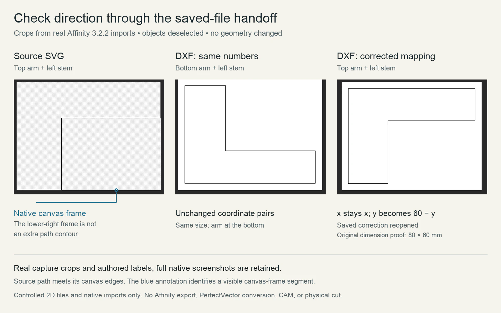
The correction was a file-level mapping for this particular 60-unit-high, zero-origin plane:
x_dxf = x_svg
y_dxf = 60 - y_svg
For example:
| Source SVG point | Corrected DXF point |
|---|---|
Top-left: (0, 0) | (0, 60) |
Inner corner: (25, 20) | (25, 40) |
Bottom-left: (0, 60) | (0, 0) |
Independent inspection confirmed that both DXFs contain one closed polyline with six vertices and coordinate bounds from 0 to 80 in X and 0 to 60 in Y. The size stayed the same while the arm changed sides vertically. Applying the same reflection twice returns the original point list, which is why adding another flip can undo a correct handoff.
These are original authored controls, not an SVG exported to DXF by Affinity or a PerfectVector conversion. We tested native file imports and the saved correction. We did not test a GUI flip/export command, CAM setup, machine operation, or physical cut.
Do not copy the constant 60 into an unrelated drawing. A different origin, plane, or transformation needs its own mapping. Complex DXF entities also need an entity-aware conversion; replacing every Y-looking number in a file is not this controlled correction.
Diagnose your own logo without damaging the master
You need the approved source image or vector, an untouched copy of the DXF, and the receiving application's intended plane/view and unit settings. If someone else supplied the file, request those details with the supported DXF version.
- Choose a direction reference. Mark one feature at the top and one on a particular side. For lettering, inspect a word whose reversed form is obvious. Keep that reference beside the file you are checking.
- Open the saved DXF in a fresh document. Use the intended import units and a known view of the artwork's plane. Compare the reference before arranging the logo or applying production operations.
- Locate the first mismatch. Compare the raster, the approved vector reference if one exists, and the imported DXF. If the reference is already reversed, correct that earlier stage. If only a viewing direction differs, establish the intended view before editing the geometry.
- Correct the responsible handoff once. When a source-to-destination axis mismatch is confirmed, have the export or conversion workflow apply the appropriate coordinate mapping. If a supplied DXF needs correction, work in a separate copy and preserve the source. Do not repeatedly mirror the master to compensate for an unverified setting.
- Reopen the saved result. Compare both landmarks, a known width and height, and the required contour structure. A corrected-looking open document is not enough if the saved delivery file reimports differently.
In our example, the completion check was the corrected file's native reimport: top arm, left stem, 80×60 mm. For your job, run the equivalent check in the actual receiver. A design-tool import does not prove that a CAM system or machine will interpret the job correctly.
Keep accidental reflection separate from intentional mirroring
A DXF whose direction changed unexpectedly is a file-handoff diagnosis. Deliberate mirroring for a transfer or reverse-side process is a production decision based on how the finished artwork will be viewed.
Use the HTV and adhesive-vinyl mirroring guide for transfer-side decisions, and the back-engraving orientation guide for artwork viewed through the opposite face. Keep the approved front-view reference separate from an intentionally mirrored production copy.
Correct an accidental handoff reversal before deciding whether the manufacturing process requires another transformation. Otherwise, an extra mirror can hide one mistake while introducing another.
Where PerfectVector fits for an image-only logo
PerfectVector fits when the surviving logo is a PNG or JPG and you need vector outlines for a DXF handoff. Start with the source logo, compare the vector preview with its approved direction, then inspect the exported DXF in your receiver. Check the top, side-specific details, dimensions, and contours before using it in a job.
If you already have a usable SVG, DXF, or native CAD master, repair the relevant handoff from that source. Retracing an image of good geometry adds a reconstruction step and does not diagnose the coordinate mismatch. Keep machine settings and final production verification in the receiving workflow.
FAQ
Can a DXF have the right size and still be reflected? Yes. Our two DXF controls kept the same 80×60 coordinate bounds, but the unchanged-coordinate import put the horizontal arm at the bottom. Compare an asymmetric landmark as well as dimensions.
Should I rotate a mirrored logo 180 degrees? First determine whether it is reflected or rotated. A one-axis reflection and a half-turn change different relationships. Check a top feature and a side feature against the approved source before choosing a correction.
Does every DXF use a Y-up coordinate system? Do not assume one universal screen direction. DXF entities can use different coordinate systems, and plane and viewing direction affect interpretation. Our demonstrated correction applies only to the simple 2D control and native imports described here.
Sources
- W3C — SVG coordinate systems, transformations and units — Defines SVG's initial top-left origin, axis directions, viewBox mapping, and additional transformations.
- Autodesk — AutoCAD 2012 DXF Reference — Documents legacy DXF entity coordinates and world/object coordinate distinctions; see the Object Coordinate Systems section.
- W3C — CSS Transforms Level 1 — Separates axis flips from rotation in the mathematical treatment of transformations.
Only have the raster logo? Start free with your own image in PerfectVector. Compare the preview's direction with the original, then reimport the exported DXF and check its landmarks and dimensions before preparing the job.
More from the blog
Seam Allowance: Offset the Pattern, Don't Scale It
See why enlarging a sewing pattern does not add equal seam allowance. Measure original SVG examples, distinguish corner joins, and keep the seam line unchanged.

Resize a Rhinestone SVG Without Changing Hole Size
Learn when to restore a rhinestone SVG's import size and when to rebuild its layout. Keep hole diameters fixed, check spacing, and test with your actual stones.