Image to SVG for Shaper Origin: Clean Cut Paths
Convert a suitable image into a Shaper Origin SVG, preserve real-world size, assign cut types, inspect closed paths, and test the file before routing.
On this page
- What makes an SVG usable in Shaper Origin?
- 1. Choose an image that can become sensible toolpaths
- 2. Convert the raster image into SVG paths
- 3. Restore and verify real-world size
- 4. Clean paths according to the operation
- Close profiles that need an inside, outside, or pocket cut
- Keep intentional open paths open
- Simplify cautiously
- 5. Assign Origin cut types after the geometry is stable
- 6. Import, preview, and run a small test
- Common image-to-Origin failures
- When not to vectorize the image
- FAQ
- Sources
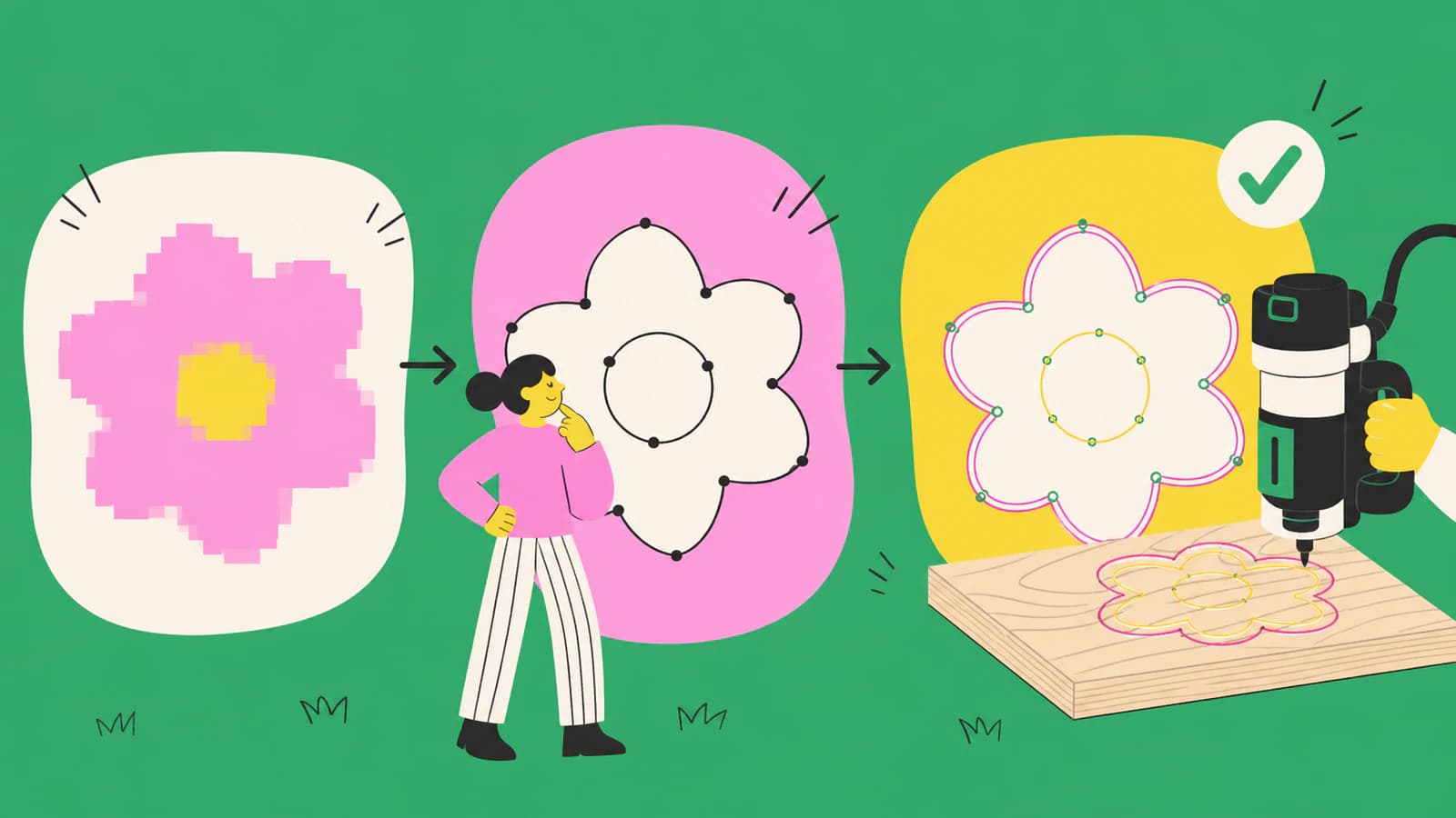
To convert an image to SVG for Shaper Origin, start with flat artwork, rebuild its visible regions as vector paths, and then prepare those paths for the job. The conversion is only the first half. Before routing, confirm the file's physical size, remove stray geometry, close any profile that needs an inside, outside, or pocket cut, and assign Origin's color-coded cut types.
Use a raster-to-vector workflow for logos, silhouettes, line art, signs, and simple inlays. Keep a photo as a reference or redraw it when tonal detail, precise joinery, or dimension-critical geometry matters more than its outline.
The short answer
- Convert a clear PNG or JPG into real SVG paths.
- Set the document in inches or millimeters and verify one known dimension.
- Clean open gaps, doubled edges, background shapes, and excess nodes.
- Assign guide, online, inside, outside, or pocket intent with Origin's current cut-type encoding.
- Import or sync the SVG, check the on-tool preview, and test the critical feature on scrap.
What makes an SVG usable in Shaper Origin?
Origin accepts SVG files, but the extension alone does not make a file ready to cut. Shaper's SVG Files Basics separates pixel images such as JPEG and PNG from vector shapes and recommends real-world units with RGB color mode.
A useful Origin file needs four things:
| Requirement | Why it matters | Quick check |
|---|---|---|
| Real vector paths | Origin follows geometry, not a pixel preview | Select a shape in a vector editor and inspect its nodes |
| Known physical size | A clean path can still import at the wrong scale | Measure one dimension after import |
| Intentional open or closed geometry | Inside, outside, and pocket cuts need a boundary | Follow each important contour around to its start |
| Cut-type assignment | Color tells Origin how to interpret a path | Compare the on-tool result with your operation plan |
The order matters. Do not color-code a noisy trace and assume it is finished. First decide which contours belong in the job, then give those contours meaning.
1. Choose an image that can become sensible toolpaths
The best sources already look like shapes: a high-contrast logo, a bold silhouette, a simple badge, or line art with deliberate gaps. Large, sharp artwork gives the conversion more useful edge information than a small screenshot or compressed thumbnail.
Pause before converting when the source contains:
- shadows, reflections, or photographic texture;
- tiny lettering that will be smaller than the cutter can reproduce;
- several nearly identical colors that do not represent separate operations;
- perspective distortion in an object that must remain square;
- joints, pockets, or dimensions that should be drafted precisely.
An automatic trace reconstructs visible boundaries. It does not know that two lines should be parallel, that a mortise needs a specific clearance, or that a decorative mark should be ignored. Draft dimension-critical geometry in CAD or Shaper Studio and use vectorization only for the illustrative portion.
2. Convert the raster image into SVG paths
Crop away the background and correct obvious rotation or perspective first. If the source has a white rectangle behind the artwork, remove it before conversion or delete the resulting background path afterward.
For suitable flat artwork, convert the image into SVG or DXF for CNC. PerfectVector reconstructs the image as editable shapes; it does not assign Origin cut types or choose router settings. Download the SVG, open it in a vector editor, and separate the contours you intend to route from decorative or unwanted regions.
Inspect the file at two zoom levels:
- At normal size, confirm the silhouette and negative spaces read correctly.
- At high zoom, look for stair-stepped curves, isolated specks, doubled boundaries, tiny loops, and too many nodes.
If the trace follows both sides of a thick drawn line, you have an outlined band rather than one center path. That may be correct for a pocket or shape, but it is wrong when you intended a single engraving line. In that case, use centerline tracing, redraw the line, or capture the drawing with a centerline-aware workflow.
3. Restore and verify real-world size
Set the SVG document units to inches or millimeters and enter the intended width or height. Scale the artwork uniformly. Then check a second dimension or add a temporary reference square before export.
This step is separate from tracing. A vector can preserve proportions while still opening at a surprising physical size because applications map SVG coordinates and units differently. If that happens, the diagnosis in why an SVG imports at the wrong size helps separate a global unit mismatch from distorted geometry.
For a photographed sketch, include a ruler or known-size rectangle in the same plane as the drawing. Shaper Trace offers another route for physical drawings: Shaper says its frame-and-camera workflow produces a one-to-one SVG and can capture either outlines or centerlines. The current Shaper Trace overview is the authoritative reference for that product workflow.
Remove any temporary calibration mark before the final cut file unless it is intentionally coded as a guide.
4. Clean paths according to the operation
Path cleanup should follow the cut plan, not a generic goal of having the fewest possible nodes.
Close profiles that need an inside, outside, or pocket cut
Shaper's Cut Type Encoding explains that open shapes can be guide or online cuts, while inside, outside, and pocket behavior requires closed shapes. At high zoom, follow each important boundary through corners and joins. Repair small gaps and remove overlaps that make the same edge appear twice.
Keep intentional open paths open
An engraving stroke or layout guide may be intentionally open. Do not close it merely to satisfy a blanket preflight rule. Confirm that it is a single path rather than the two sides of an outlined stroke.
Simplify cautiously
Delete specks and points that only reproduce pixel noise. Preserve nodes that define a corner, a small recess, or the character of a curve. If editing is slow or a curve looks lumpy, use the checks in why an SVG has too many nodes before applying aggressive simplification.
5. Assign Origin cut types after the geometry is stable
Origin uses color-coded vector shapes to suggest how each path should behave on-tool. The official encoding guide distinguishes:
- guide for alignment or information you do not plan to cut;
- online for following the path center, including engraving;
- outside for keeping the positive shape to the specified dimensions;
- inside for cutting a hole to the specified dimensions;
- pocket for clearing material within a closed boundary.
Use the current palette from Shaper's documentation or encode the intent in Shaper Studio. Do not approximate the colors by eye from an old screenshot. The same guide notes that stroke width in the design file does not set the router's cut width, so a thick-looking SVG stroke is not a substitute for choosing the cutter and operation.
Color is a starting instruction, not permission to skip review. Confirm every path on the tool. An outside contour accidentally coded as inside can change the finished size by a cutter diameter.
6. Import, preview, and run a small test
Shaper's Design for Origin tutorial hub includes current workflows for Studio, Illustrator, Fusion 360, and other design tools. Whichever route you use, make the final on-tool review explicit:
- Confirm the width and height.
- Check that all intended contours appear once.
- Verify each guide, online, inside, outside, and pocket assignment.
- Inspect small holes and tight inside corners against the cutter diameter.
- Set cut depth and cutter details for the material and job.
- Test the smallest or most critical feature on scrap.
SVG geometry cannot choose feed technique, depth, cutter, workholding, or material behavior for you. Treat the test as part of file preparation, not as an optional last-minute check.
Common image-to-Origin failures
| Symptom | Likely cause | Best next check |
|---|---|---|
| Origin shows an unexpected extra rectangle | The raster background became a path | Delete the background shape in a vector editor |
| A thin line appears as two contours | Boundary tracing followed both edges | Use an online center path or redraw the line |
| Inside or pocket is unavailable | The contour is open | Join the endpoints and inspect for overlaps |
| The part imports at the wrong size | Units or document dimensions changed | Reset one known dimension and verify another |
| Curves look nervous or editing is slow | Pixel noise became dense nodes | Simplify selectively or start from a cleaner source |
| Cut intent looks wrong on-tool | Colors were approximate or assigned too early | Reapply the documented cut-type encoding |
When not to vectorize the image
Keep or redraw the source when:
- it is a photograph meant only as visual reference;
- the geometry controls a joint, fit, or safety-critical dimension;
- the design depends on shading rather than regions or lines;
- tiny details fall below practical cutter size;
- a native CAD file or original vector already exists.
If the original vector exists, repair or export it instead of tracing a raster copy. If a precise part must be recreated from a drawing, use the scan as an underlay and draft the geometry with dimensions.
FAQ
What file format does Shaper Origin use? Shaper's documentation says Origin cuts SVG files. Prepare real vector paths, use real-world units, and check the current RGB cut-type encoding before routing.
Can I convert any photo into a Shaper Origin SVG? You can trace a photo, but that rarely creates sensible toolpaths automatically. Flat logos, silhouettes, and line art are better candidates. Redraw dimension-critical geometry and keep tonal photos as references.
Why can I not choose an inside or pocket cut? The contour may be open. Origin needs a closed shape to identify inside and outside. Join the intended endpoints, remove overlaps, and check that the path forms one continuous boundary.
Does SVG stroke width control the router cut width? No. Shaper's cut-type guide says the design stroke width does not change the resulting cut width. The cutter and on-tool operation determine the physical result.
Should I use Shaper Trace or an image vectorizer? Use Shaper Trace when you have a physical drawing and want its framed, one-to-one outline or centerline capture. Use a raster-to-vector converter when you already have a suitable digital image and want to inspect editable paths before importing.
Sources
- Shaper Tools — SVG Files Basics — Origin's SVG workflow, vector-versus-raster distinction, real-world units, and RGB guidance.
- Shaper Tools — Cut Type Encoding — guide, online, inside, outside, and pocket behavior plus open/closed path requirements.
- Shaper Tools — Shaper Trace — one-to-one capture, outline and centerline modes, and the current physical-drawing workflow.
- Shaper Tools — Design for Origin — current design and file-preparation tutorials across supported workflows.
Have a flat logo, silhouette, or drawing ready to test? Convert it into SVG or DXF for CNC, inspect the paths and scale, then assign Origin cut types only after the geometry passes your preflight.
More from the blog

Convert an Image to SVG With Clean CNC Cut Paths
A CNC follows vector paths, not pixels, so your design has to become a clean SVG or DXF first. Here's how to convert an image into CAM-ready, closed-path vectors.

PNG to SVG for Bambu Studio: Clean Multicolor Imports
Convert a PNG to SVG for Bambu Studio, preserve useful color regions, check closed paths and holes, then verify size and extrusion before you slice the model.